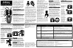
background image

Honeywell

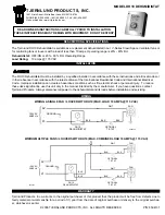
THESE HUMIDITY CONTROLLERS PRO-
VIDE AUTOMATIC CONTROL OF A HU-

MIDIFIER OR A DEHUMIDIFIER FOR DE-
HUMIDIFICATION AND MILDEW CON-

TROL IN AIR CONDITIONING SYSTEMS.
ALL MODELS ARE SUPPLIED WITH COV-

ER AND CONTROL KNOB FOR WALL
MOUNTING.

❑ 

C o v e r   o f   i m p a c t - r e s i s t a n t ,   m o l d e d

plastic.

❑ 

Sensing element of thin, moisture sensi-

tive nylon ribbon provides reliable opera-
tion even when ambient temperature con-
ditions change.

❑ 

Fully enclosed, dust-free, spst, snap

switch.

❑ 

Large, easy-to-read 

 on face

of controller.

❑ 

Positive ON and OFF setting positions

permit manual operation of the controlled
equipment.

Form Number 

60-2097—2

REV. 

 Inc. 1987

Summary of Contents for H46C-F

Page 1: ...ALL MOUNTING Cover of impact resistant molded plastic Sensing element of thin moisture sensi tive nylon ribbon provides reliable opera tion even when ambient temperature con ditions change Fully enclosed dust free spst snap switch Large easy to read scaleplate on face of controller Positive ON and OFF setting positions permit manual operation of the controlled equipment S M Form Number 60 2097 2 R...

Page 2: ...set point OR ELEC SCREW MODELS makes at set point less differential 20 80 10 60 TRIC CORD TYPE H46Ca x x x H46Da x x x H46Eb x x Note b H46Fb x x Note b alncludes adapter plate for vertical switch box mounting blncludes 6 ft 1 8 m electric cord H46E F have interrupter plug continued on page 3 WHEN PURCHASING REPLACEMENT AND MODERNIZATION PRODUCTS FROM YOUR TRADELINE WHOLESALER OR YOUR DISTRIBUTOR ...

Page 3: ... II 1 7 34 9 I I 3193A IG 2 INSTALLATION DIMENSIONS IN in mm IN BRACKETS FOR H46E F WHEN INSTALLING THIS PRODUCT 1 Read these instructions carefully Failure to follow them could damage the product or cause a hazardous condition 2 Check the ratings given in the instructions and on the product to make sure the product is suitable for your application 3 Installer must be a trained experienced service...

Page 4: ...itioning energy higher temperature set point and still prevent mildew by use can be oDtimized The dehumidistat and thermostat controlling humidity For wiring diagrams See Figs 3 should be w ired in parallel such that by leaving the and 4 Q539A T87F INTERNAL SCHEMATIC I FILTER L T I I I I I HEAT OFF COOL HEAT oFF COOL i J v 1 q A B o w Y I I I I 4I HEATING RELAY OR VALVE COIL I COOLING FAN CONTACTO...

Page 5: ...EQUIRE 2 I IG 5 TYPICAL WIRING DIAGRAMS FOR H46D F SINGLE SPEED FAN MOTOR HUM IOITY H46C E EN POWER SUPPLY PROVlDEDlSCOt4NECT MEANS ANC10VERLOAD PROTECTION AS REQUI RED 2569C FIG 6 TYPICAL WIRING DIAGRAM FOR H46C E A A A L COOLING RELAY R8230 FAN CONTROL L4068 1 J F FAN MOTOR I AJ PROVIOE DISCONNECT MEANS ANO OVERLOAD PROTECTION AS REQUIRE r S W I T C H S688A 3 TO ENSURE HUMIDIFIER OPERATION IN WI...

Page 6: ...ol knob counter clockwise n to the stop H46D F HUMIDITY CONTROLLERS The H46D and F switches make contact on a humidity fall to the set point minus the differential In most humidifier systems the furnace fan must be operating before the humidifier starts An increase in humidity to the set point breaks the switch contacts Turn control knob clockwise n to the stop for ON position Set to the OFF posit...

Reviews: