Honeywell GENT, Operating Instructions Manual
The Honeywell GENT Operating Instructions Manual is your essential guide to understanding and using our remarkable product. This comprehensive manual provides detailed instructions and troubleshooting tips for seamless operation. Download this manual for free from our website manualshive.com, ensuring a hassle-free experience with your Honeywell GENT.
Share
Download


Reviews:
No comments
Related manuals for GENT
2
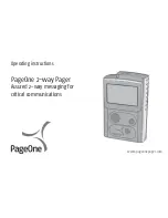
Brand: PageOne Pages: 24
G Series
Brand: unication Pages: 19
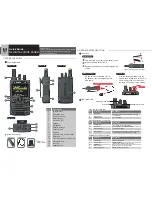
G4
Brand: unication Pages: 14
G4
Brand: unication Pages: 2
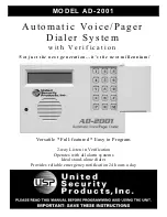
AD-2001
Brand: United Security Products Pages: 16

Advisor Graphix
Brand: PageOne Pages: 28
Alpha Elite
Brand: PageOne Pages: 42

CC28
Brand: CallToU Pages: 10
PG-2106FS
Brand: Pocsag Pages: 12
s.QUAD X15
Brand: SwissPhone Pages: 2
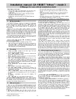
CA-1803BT Athos
Brand: jablotron Pages: 6
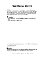
DE 506
Brand: SwissPhone Pages: 18
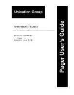
NP88 POCSAG
Brand: Unication Group Pages: 14
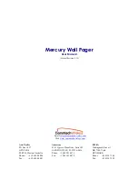
Mercury Wall Pager
Brand: commtech wireless Pages: 10
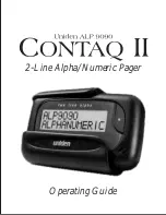
Contaq II ALP 9060
Brand: Uniden Pages: 36

PPCC01
Brand: Pudu Pages: 15
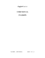
PG-2568PS
Brand: Eagle Patriot Pages: 12
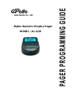
AL-A29
Brand: Apollo Pages: 23


