GB
ExitLED PRO
Honeywell Life Safety AS, Po. Box 3514, N-3007 Drammen, Norway
http://www.hls-nordic.com
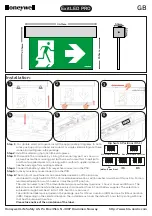
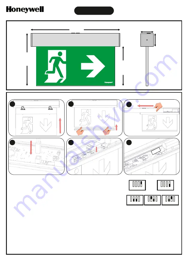
Installation:
DS1
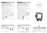
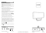
Step 6:
The control of maintained or non maintained operation of the luminary
is achieved through Switch 4 of DS1. For maintained operation, switch number 4 must be in ON position. For non-
maintained operation, switch number 4 must be in OFF position.
Step 5:
In case you use a module connect it on the PCB.
Step 4.
Connect the battery cable to its respective connector on the PCB.
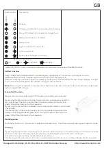
Two additional labels are included in the package, one for 3 hours duration (180) and one for 8 hour duration
(480). Depending on the selected duration, the installer must cover the default 1 hour (60) printing with one
that has the required duration.
Please take notice of the orientation of the label.
The user can select one of the 3 available minimum autonomy durations: 1 hour, 3 hours and 8 hours. The
selection must be done while the luminaire is disconnected from AC and battery supplies. The selection is
achieved through Switches 2 & 3 of DS1. Switch 1 is not used.
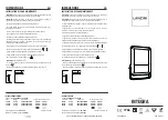
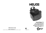
Step 1:
For double sided pictogram, install the appropriate pictograms to both
sides, push up until you hear click sound. For single sided pictogram, there
is one blind pictogram in the package.
Step 2:
Install the retaining clip to hold the pictograms.
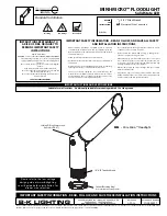
Step 3:
Dismantle the luminaire by sliding the mounting part as shown in
picture. Fasten the mounting part (with screws from within) to wall (with
or without supplied spacers) or ceiling (with or without supplied spacers).
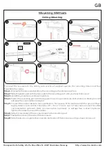
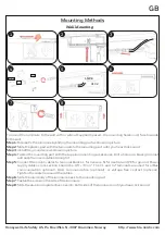
See the next page for mounting methods.
5
6
4
2
1
3
50mm
50mm
347mm
205mm
155mm
804029000
Maintained operation
ON
1 2 3 4
ON
1 2 3 4
Non-maintained operation
ON
1 2 3 4
ON
1 2 3 4
ON
1 2 3 4
1h
(default position)
3h
8h
Dip Switch Positions (DS1)