

Document 800-07497V1 – Rev A – 02/2014
Document 800-07497V1 – Rev A – 02/2014
equIP
®
Series
True Day/Night Rugged IP Minidome Camera
Quick Install Guide
Introduction
Thank you for purchasing a Honeywell equIP Series True Day/Night Rugged IP
MInidome Camera. Before installing the camera, please read this guide carefully and
verify your model:
HD4MDIH/HD4MDIHX, 720p resolution, 3.3 - 12 mm Vari-focal Auto Iris lens
For detailed information for your specific camera, please refer to the appropriate user
guide
located on the IP Utility DVD. When you install the Honeywell IP Utility software,
the User Guide will automatically be downloaded to your computer.
Before installing the camera, Honeywell recommends that you download the latest
software updates. Go to
http://www.honeywellsystems.com/support/download-center/
and follow the instructions on the page to log on, find your camera, and then
download software updates.
Preparing the Mounting Surface
Note
To prevent moisture from entering the housing, position the enclosure with the side conduit entry
pointing down.
Note
The housing is intended for mounting on a flat surface only.
1.
Use the mounting template to mark the mounting surface for the screw holes and the cable access
hole.
2.
Pre-drill holes in the mounting surface as required.
Installing the Conduit Plug
The HD4 equIP Series camera ships with
the conduit plug pre-installed in the
enclosure base back conduit entry. To use
the back conduit entry, remove the conduit
plug and install it in the side conduit entry
after loosening the locking screw. (See
Top
View
in
Adjusting the Camera
in
Camera
Installation
.) Retighten the locking screw to
secure the conduit plug in place.
Note
For secure installations, protect
surface-mounted cables with
plastic or metal cable covers.
Preparation
Black tabs (x4)
Black clips (x4)
Metal
hinge
Mounting
holes
Gimbal
Dome bubble
Turret
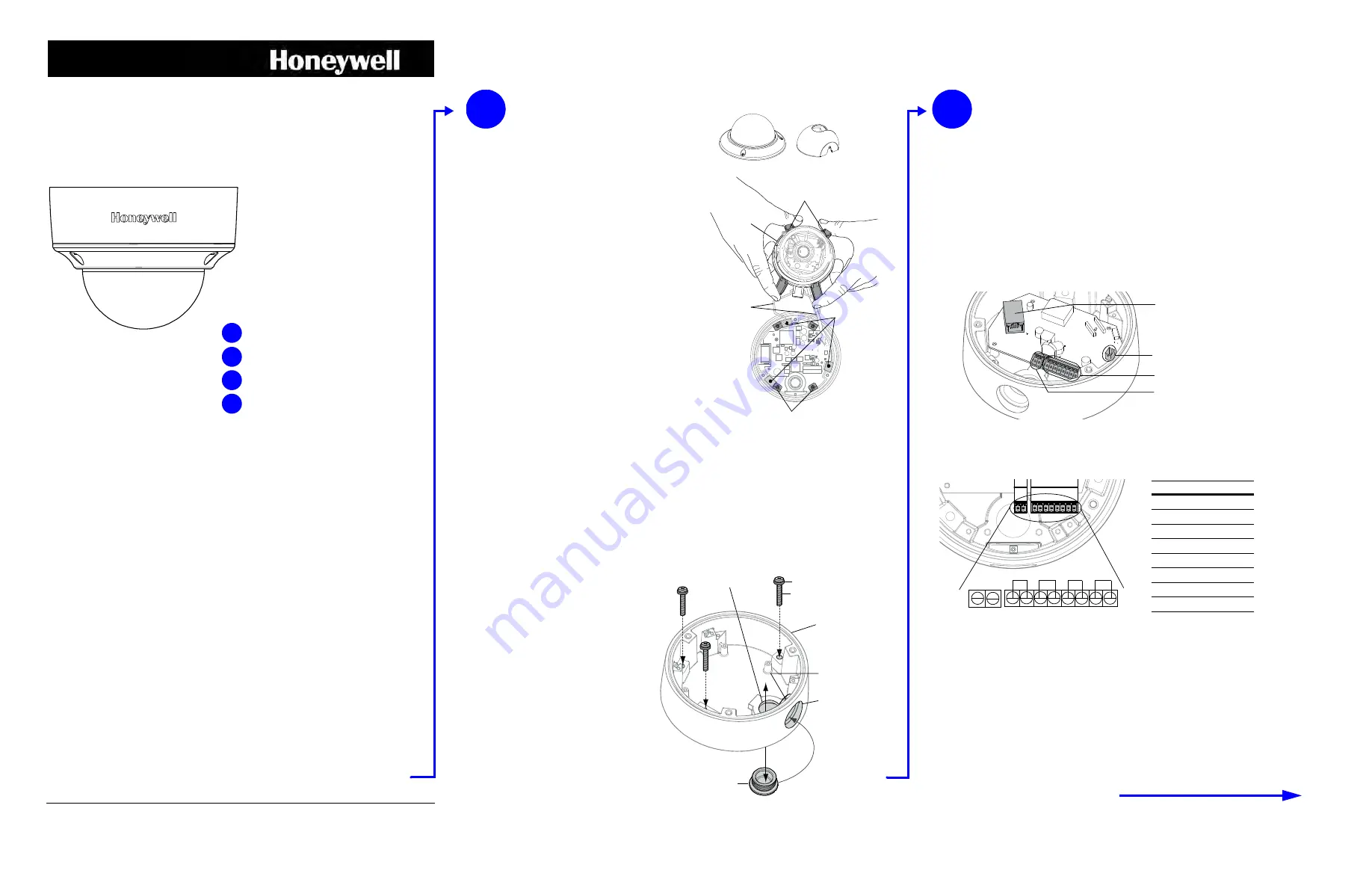
Removing the Dome Bubble and
Turret
1.
Using the supplied Allen key, loosen the captive
screws on the dome bubble. Remove the dome
bubble and set it aside.
2.
Gently pull the turret off the gimbal, then set it aside.
Removing the Gimbal
Remove the gimbal from the enclosure base so you can
easily access the mounting holes (see illustration).
1.
Squeeze the 4 black tabs until they are free of the
black clips.
2.
Elevate the hinge until the gimbal is above the
housing and you have access to the enclosure base
mounting holes.
Caution
When elevating the hinge, do not overstress the
two ribbon cables.
If necessary, rotate the gimbal to provide
additional slack.
1
Side
conduit
entry
Back conduit entry
Enclosure base
Conduit
plug locking
screw
Conduit plug
Screws
Rubber washer
Please turn over
Preparation
Camera Installation
Network Setup
Camera Operation
1
2
3
4
Camera Installation
2
Mounting the Camera
1.
Route the cables through your chosen conduit entry.
2.
Mount the camera to a wall or ceiling using the supplied screws.
If you are using screws other than those supplied by Honeywell, then please remove the rubber
washers from the Honeywell-supplied screws, and then install them under the head of each of
your screws. See the
illustration.
Connecting the Wiring
1.
Connect the power input:
•
For 24 V AC connection, locate the two-pin green connector that was shipped with
your camera and make the necessary connections.
•
For PoE connection, connect a CAT5 cable to the RJ45 network connector.
Note
It is not recommended that you supply both 24 V AC and PoE at the same time.
2.
Connect the alarms and audio:
Locate the eight-pin green connector that was shipped with your camera and make all the
necessary connections as shown in the table below.
3.
Connect to the network:
If you haven’t already connected a CAT5 cable to the RJ45 network connector for PoE,
then connect a CAT5 cable to the RJ45 network connector.
Note
For detailed audio and alarm configuration information, refer to the Refence Guide for
your camera located on the IP Utility DVD.
Sealing the Wiring
To prevent moisture from entering the housing, if you are using the back conduit entry, apply
sealant around the conduit connection and the mounting screws.
Power:
24 V AC
RJ45 Ethernet
network connection
Audio/Alarms
Local video out
(adjusting and focusing)
In
Out
Audio
Alarm
In
Out
24 V AC
1
2
3 4
5
6
7
8
PIN
Definition
1
Audio In +
2
Audio In –
3
Audio Out +
4
Audio Out –
5
Alarm In +
6
Alarm In –
7
Alarm Out +
8
Alarm Out –
HD4MDIH(X)
Operating Notes
Power Supply
This dome camera can operate on 24 V AC or PoE.
Operating Conditions
Avoid:
•
Viewing bright objects (for example, light fixtures) for
extended periods
•
Operating or storing the unit in the following locations.
•
Extremely humid, dusty, hot/cold environments (where
the operating temperature is outside the recommended
range of -22°F to 140°F
[-30°C to +60°C])
•
Close to sources of powerful electromagnetic radiation,
such as radio or TV transmitters
•
Close to fluorescent lamps or objects reflecting light
•
Under unstable light sources (may cause flickering)


