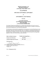
Honeywell BENDIXKing APEX EDGE Series, Pilot'S Manual
The Honeywell BENDIXKing APEX EDGE Series Pilot's Manual is a comprehensive guide for aviation enthusiasts. This user-friendly manual provides essential information for operating the APEX EDGE Series with precision and confidence. Download the free manual from manualshive.com and unlock the full potential of this exceptional product.
Share
Download


Reviews:
No comments
Related manuals for BENDIXKing APEX EDGE Series

G500
Brand: Garmin Pages: 2
G500
Brand: Garmin Pages: 334
SkyEcho
Brand: uAvionix Pages: 10
Cessna Caravan G1000
Brand: Garmin Pages: 33

Mobile 20
Brand: Garmin Pages: 2
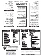
APOLLO GX60
Brand: Garmin Pages: 2

GI 275
Brand: Garmin Pages: 2
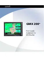
GMX 200
Brand: Garmin Pages: 16
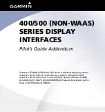
GPSMAP 400 series
Brand: Garmin Pages: 28

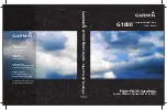
G1000H
Brand: Garmin Pages: 136

Cirrus Perspective SR20
Brand: Garmin Pages: 128

Approach G5 - GPS-Enabled Golf Handheld
Brand: Garmin Pages: 168
Cessna Caravan G1000
Brand: Garmin Pages: 482
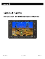
G900X
Brand: Garmin Pages: 681
Lynx NGT-9000
Brand: L3 Aviation Products Pages: 27
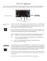
STX 165
Brand: Dallas Pages: 8

Indu Variometer
Brand: Kanardia Pages: 18
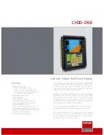
CHDD–268
Brand: Barco Pages: 2


