background image

N

Bendix/King
Silver Crown Plus

Avionics Systems
Pilot’s Guide

Audio Panel Systems
Communication Transceivers
Nav/Comm Systems
Navigation Receiver
DME Systems
ADF System
Transponders

N

Silver Crown Plus R4  11/18/02  1:00 PM  Page 42

Summary of Contents for Bendix/King Silver Crown Plus

Page 1: ...Silver Crown Plus Avionics Systems Pilot s Guide Audio Panel Systems Communication Transceivers Nav Comm Systems Navigation Receiver DME Systems ADF System Transponders N Silver Crown Plus R4 11 18 02 1 00 PM Page 42 ...

Page 2: ...port of this document review for export license requirement is needed COPYRIGHT NOTICE 1998 2012 Honeywell International Inc All rights reserved Reproduction of this publication or any portion thereof by any means without the express written permission of Honeywell International Inc is prohibited For further information contact the Manager Technical Publications Honeywell Business General Aviation...

Page 3: ...eiver Stereo Intercom System With Bluetooth Connectivity 13 KY 196A KY 197A and KY 196B VHF Communications Transceivers 23 KX 155A and KX 165A VHF Communication Navigation Transceiver 29 KN 53 Silver Crown TSO d Navigation Receiver 37 KN 62A and KN 64 TSO d Silver Crown Digital DMEs 39 KR 87 Silver Crown ADF System 41 KT 76C Bendix King Panel Mounted Transponder 45 KT 70 and KT 71 Panel Mounted Tr...

Page 4: ...s System are covered in separate publications Choose the publication pertaining to your installation from the list below Description Publication Part Number KMD 150 Multi Function Display GPS 006 18220 0000 KLN 94 GPS Navigation System 006 18207 0000 KLN 89B GPS Navigation System 006 08786 0000 KLN 90B GPS Navigation System 006 08772 0000 KMD 550 850 Traffic Addendum 006 18238 0000 ...

Page 5: ... the unit fail The PA position may be selected when the aircraft is configured with the KMA 26 driving a dedicated passenger address speaker The KMA 26 has an Auto Com feature which always provides automatic headphone audio selection to match the Com transmitter in use Thus you may change the Microphone Selector Switch without having to reselect the corresponding Com receiver button in order to he...

Page 6: ...lected on the Microphone Selector Switch then Com 1 audio is routed to the speaker This feature may be used for example if you are listening to ATC on Com 1 through the headphones and wish to monitor ATIS information from Com 2 in the background through the speaker With the Microphone Selector Switch in the Com 1 position for ATC communications pressing the MONI button routes Com 2 tuned to ATIS a...

Page 7: ...egins to speak It may optionally be installed for keyed activation where a separate microphone switch must be keyed to activate the intercom In order to set the proper VOX sensitivity momentarily press and release the left inner knob when no one is speaking into their microphones The VOX sensitivity should be set if a background hissing sound is heard in the headphones or if intercom communication...

Page 8: ...obs on the KMA 26 control intercom volume only not the receivers volume Auxiliary Music Inputs The KMA 26 can accommodate two music inputs for the listening enjoyment of crew and passengers The music input is muted quickly when radio communications are received and then gradually returns to its previous volume The KMA 26 can also be configured at the time of installation to either have or not have...

Page 9: ...latched type switches When one of these buttons is pressed it will stay in the in position Press the switch again and it be in the out position and remove that receiver from the audio Key click The KMA 28 is equipped with an electronic click to provide additional feedback for button operation To activate the key click push and hold BOTH COM 1 and COM 2 receiver buttons for five seconds and release...

Page 10: ...c selector mode Audio from the selected transceiver is automatically heard in the headsets and speaker You can check this function by switching from Com 1 to Com 2 and watch the selected audio light on the selector change from COM 1 to COM 2 This ensures the pilot will always hear the audio from the transceiver he is transmitting on When transmitting the COM 1 or COM 2 LED in the KMA 28 audio sele...

Page 11: ...permits intercommunication when desired between the crew Pressing the ICS button again disables this crew intercom function Telephone Mode The TEL position fully CW on the mic selector switch is the pilot s hook switch This is active only when the system is interfaced to an appropriate approved system such as the AirCell system Placing the mic selector in TEL places the pilot microphone and headph...

Page 12: ...mal For optimum microphone performance Honeywell recommends installation of a Microphone Muff Kit from Oregon Aero 1 800 888 6910 This will not only optimize VOX acoustic performance but will improve the overall clarity of all your communications Volume Control The volume control knob adjusts the loudness of the intercom for the pilot and copilot only It has no effect on selected radio levels musi...

Page 13: ...smission Entertainment 1 is Muted Popilot and passenger intercom Entertainment 1 Passenger and Copilot intercom Entertainment 2 Phone Booth mode Pilot has exclusive use of the telephone In TEL Pilot connected to Com 1 for PTT TX and receive This mode allows the pilot to communicate without the others bothered by the conversations Copilot and passengers can continue to communicate and listen to mus...

Page 14: ...roake or sing along mode which inhibits the soft mute feature This allows the music to continue uninterrupted by intercom or radio traffic when cockpit workload is appropriate Pushing the button again will release the mute inhibit function The passenger music source 2 can be placed in the Karaoke mode if a remote switch is installed in the aircraft Marker Beacon Operation The Marker Beacon Receive...

Page 15: ...witch the pilot selects TEL on the mic selector Any passenger who places their switch into the offhook position will also have access to the phone and all four passengers will hear the conversation In ISO intercom mode when the KMA 28 is in the TEL mode the pilot position is in the Phone Booth Only the pilot will hear the telephone and only he will be heard He will also have access to Com 1 and wi...

Page 16: ...Silver Crown Plus Pilot s Guide 12 This page intentionally left blank ...

Page 17: ...oving power the KMA 30 is in Fail Safe mode In this mode the pilot s headset is connected to COM 1 for transmit and receive and connected to unswitched input 1 for priority audio alerts The fail safe audio will only be heard in the left ear of a stereo headset Communications Transmit XMT Selection 2 To select COM 1 or COM 2 for transmit press the button on the bottom row next to the XMT legend The...

Page 18: ...e cockpit speaker when this switch is selected In Split mode the speaker carries the same audio as the pilot Depending on installation important audio alerts such as radar altimeter or autopilot disconnect will come over the speaker even if it is not selected while other unswitched inputs will only be present if the SPR button is selected Consult your professional avionics installer for these impo...

Page 19: ...ereo or mono headsets If a passenger s monaural headset is plugged in to a KMA 30 Stereo installation one channel will be shorted and all passengers will lose one channel unless they switch to the MONO mode on the headset Intercom Modes 8 The intercom has three modes ISO ALL and CRW The description of the intercom mode function is valid only when the unit is not in the Split mode In split mode the...

Page 20: ...s a service adjustment located on the top of the unit labeled MKR VOL to adjust the volume if desired The MKR button located next to the indicator lights is used to set the receiver sensitivity to test the indicator lamps and mute the marker audio Pressing the MKR button for one second will cause the marker audio to mute The next beacon received will re activate the audio Holding the MKR button fo...

Page 21: ... in 47 CFR 22 925 contain prohibition on airborne operation of cellular telephones Cellular telephones installed in or carried aboard airplanes balloons or any other type of aircraft must not be operated while such aircraft are airborne not touching the ground When any aircraft leaves the ground all cellular telephones on board that aircraft must be turned off Utility Jack The 2 5 millimeter 3 32 ...

Page 22: ...transmission is active The MUSIC function controls how music is distributed in your airplane There are two music sources available to the KMA 30 in addition to the Bluetooth stream Music 1 input at the rear connector and Music 2 is wired into the rear connector The volume of the function selection annunciations and recorder playback can be adjusted through a hole on the top of the unit marked ANN ...

Page 23: ... mode switch Therefore even in the CREW mode the passengers will hear Music 1 although though they will not hear the crew intercom or radios This mode allows you to use a single in flight entertainment source The music muting follows the front panel MUTE mode When you press MUSIC function again for a second you ll hear Alternate Music Distribution In this mode Music 2 will be heard only when the i...

Page 24: ...usic MUTE LED is OFF Annunciation is Intercom mute Mute Off The Karaoke mode music will not mute except during radio transmissions MUTE button LED is OFF Annunciation is Mute off When the KMA 30 is turned on it always begins in crew Mute on mode The passengers intercom also has a SoftMute circuit If the passengers hear the radio or talk on the intercom the music will mute If the audio panel is in ...

Page 25: ...r up to eight messages There are no buttons to press to start recording The system automatically begins to record the instant the radio selected for transmit becomes active Only the pilot and copilot will hear the playback audio To play back the last recorded message you press and hold the COM RCV pushbutton associated with the selected radio transmitter for about one second The message must stop ...

Page 26: ... speaker To exit push Mute and SPR again This mode is also reset when power is cycled Backlighting The white text backlighting is controlled by the aircraft dimmer while the green indication LEDs are automatically controlled by the light sensor on the KMA 30 ...

Page 27: ...will display the frequencies last used in the USE and STBY standby windows To override the automatic squelch pull the ON OFF Volume knob out and judging by static noise rotate it to the desired volume level Push the knob back in to activate the automatic squelch NOTE As with all avionics the KY 196A KY 197A and KY 196B should be turned on only after engine startup This simple precaution will help ...

Page 28: ...onal remote mounted frequency transfer button may also be used to perform this flip flop function KY 196B Frequency Mode Normal Operation 1 Select a new frequency in the STBY window using the frequency selection knobs The larger knob controls changes in increments of 1MHz The smaller knob allows selection of 25kHz frequencies only when pushed in and both 8 33kHz and 25kHz frequencies when pulled o...

Page 29: ...stem is operating in the Channel Mode 6 To exit the Program Mode momentarily press the channel button The unit will also automatically exit the Program Mode if no programming occurs within approximately 20 seconds The Program Secure Mode The Program Secure Mode may be used to lock a desired frequency to a specific channel number prohibiting program changes from the front of the unit Your KY 196A K...

Page 30: ...used Direct Tune Mode The Direct Tune Mode is entered by pressing and holding the transfer button for longer than two seconds The STBY frequency will disappear and the frequency in the active window can be changed with the frequency selection knobs Momentarily pushing the transfer button will return the unit to the Frequency Mode normal operation The STBY frequency displayed prior to entering the ...

Page 31: ...the response time is approximately eight seconds dA 1 values of 2 through 7 provide intermediate response times Display adjustment 2 dA 2 is used to vary the display brightness when ambient light conditions are less than direct sunlight such as in a dark cockpit dA 2 values range from 0 64 with 0 being dimmest and 64 being brightest the normal dA 2 setting is 20 dA 3 values range from 0 to 255 wit...

Page 32: ...Silver Crown Plus Pilot s Guide 28 This page intentionally left blank ...

Page 33: ...ersions CONTROL FUNCTION NOTE The 25 kHz and 8 33 kHz versions of the KX 165A are distinguishable from one another in two ways The 25 kHz version has PULL 25K nomenclature below the Comm Frequency Select Knobs while the 8 33 version has PULL 8 33K In addition the 25 kHz version has two digits to the right of the decimal in the Comm frequency while the 8 33 kHz version has three digits to the right...

Page 34: ...ed when incrementing or decrementing the kHz portion of the standby display KX 165A 8 33 kHz Version The inner knob will change the kHz portion of the standby display It allows selection of 25 kHz frequencies only when the knob is pushed in and both 8 33 kHz and 25 kHz frequencies when the knob is pulled out The frequency wrap around at the edge of the band is also utilized when incrementing or de...

Page 35: ...ncies that were displayed before power down The KX 155A and KX 165A also have provisions to program 32 channels Pressing the CHAN button for 2 or more seconds will cause the unit to enter the channel program mode Upon entering the channel program mode PG is displayed next to the channel number and the channel number will flash indicating that it can be programmed Figure 5 FIGURE 5 Entering channel...

Page 36: ...remote mounted channel switch may be installed that increments the next programmed channel into the standby window each time the switch is activated The unit is placed in the transmit mode by depressing the MIC KEY button The unit has a stuck microphone alert feature If the microphone is keyed continuously for greater than 33 seconds the transmitter stops transmitting and the active Comm frequency...

Page 37: ...FIGURE 11 Nav display active VOR frequency CDI format The vertical needle moves side to side similar to a mechanical CDI When the needle is centered the aircraft is on the selected OBS course When the active frequency is tuned to a VOR frequency the center of the CDI scale displays the TO or FROM indicator In the CDI mode the increment decrement knob pushed in channels the ACTIVE frequency window ...

Page 38: ...R mode bearing to function When a too weak or invalid VOR signal is received the display flags as shown in Figure 15 FIGURE 15 VOR mode active bearing flag display Another push of the mode button will cause the NAV display to go from the ACTIVE BEARING format to the ACTIVE RADIAL format as shown in Figure 16 FIGURE 16 VOR mode radial from function In the RADIAL mode the increment decrement knob ch...

Page 39: ...ushed in depressing the NAV TRANSFER button will interchange the ACTIVE and STANDBY frequencies The NAV IDENT knob is active in the pulled out position so that both voice and ident can be heard When this knob is pushed in the ident tone is attenuated The volume of voice ident can be adjusted by turning this knob Pilot Configuration This mode can be accessed by pressing and holding the Nav Mode But...

Page 40: ...tton will bring the unit up in the Direct Tune Mode 120 00MHz 120 000MHz in 8 33 kHz KX 165A will be the active COMM frequency and 110 00 MHz will be the active NAV frequency This will aid the pilot in blind tuning the radio in the unlikely event of display failure ...

Page 41: ...the displayed frequency number while a counterclockwise rotation will decrease it The larger selector knob is used to change the MHz portion of the frequency display the smaller knob changes the kHz portion in 50 kHz steps At either band edge of the 108 00 to 117 95 MHz frequency spectrum an off scale rotation will wrap the display around to the other frequency band edge i e 117 95 advances to 108...

Page 42: ...Silver Crown Plus Pilot s Guide 38 This page intentionally left blank ...

Page 43: ...an out position When in the in position this smaller knob changes the 0 1 MHz digit 0 0 0 1 0 2 etc When pulled out it adds 0 05 MHz to the frequency and tunes in 0 1 MHz steps 0 05 0 15 0 25 etc Pushing the smaller knob in subtracts 0 05 MHz from the displayed frequency The outer larger knob changes the larger digits 1 MHz 10 MHz In FREQ mode the unit will display distance and the selected freque...

Page 44: ... the top cover The unit electronically converts to distance the elapsed time required for signals to travel to and from the ground station This distance is then indicated in nautical miles on the Distance Speed Time to Station display This distance commonly referred to as slant range distance should not be confused with actual along the ground distance The difference between actual ground distance...

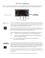
Page 45: ...KR 87 41 KR 87 Silver Crown ADF System Operating the KR 87 ...

Page 46: ...cy will become active and the former active frequency will go into standby Operating Modes Antenna ANT mode is selected and annunciated when the ADF button is in the out position ANT provides improved audio reception from the station tuned and is usually used for identification The bearing pointer in the KI 227 indicator will be deactivated and immediately turn to the 90 relative position and rema...

Page 47: ...switch to stop and start the flight timer It should be emphasized that the start stop function will only operate with power applied to the unit Always read flight time prior to power shutdown Flight time or elapsed time are displayed and annunciated alternatively by depressing the FLT ET button The flight timer continues to count up until the unit is turned off or stopped with an external switch T...

Page 48: ...t is always wise to make positive identification of the station being tuned by switching the function selector to ANT and listening for station call letters Electrical Storms In the vicinity of electrical storms an ADF Indicator pointer tends to swing from the station tuned toward the electrical discharges Location of the storm can be useful information but the erratic behavior of the pointer shou...

Page 49: ... the Air Traffic Controller Operating the KT 76C Before starting your aircraft s engine make sure that the KT 76C function selector knob or your avionics master is turned to OFF After engine start turn the function selector knob to SBY standby Give your transponder about 45 seconds to become operational Select the proper reply code by pressing the desired code entry buttons The reply code will be ...

Page 50: ...ere is no activity on any of the code entry buttons the VFR button or the CLR button for four seconds VFR Button Momentarily pressing the VFR button will enter a pre programmed VFR code typically 1200 in the code window Pressing and holding the VFR button for two seconds will cause the last active code to be displayed During installation it may be desired to set the default VFR code to a code othe...

Page 51: ...Selector Knobs selects a separate digit of the identification code Reply The lighted R reply indicator blinks when the transponder is replying to a valid interrogation and illuminates for 18 seconds after the initiation of the Ident Altitude Display The KT 70 and KT 71 display Flight Level Altitude marked by the letters FL and a number in hundreds of feet on the left side of the display For exampl...

Page 52: ...red VFR code 3 While holding the IDT Ident button in momentarily press the VFR button Function Selector Knob Function Selector Knob The Function Selector Knob on the right side of the KT 70 and KT 71 enables you to choose from among the following operating modes OFF The unit is not receiving power For the KT 70 only when the unit is turned to another mode the installerprogrammed aircraft address a...

Page 53: ... status bit is set to indicate the aircraft is on the ground In both units the ID code is shown on the right side of the display with altitude reported on the left side The letters GND are also displayed in this mode NOTE An optional remote air ground switch may be installed on the aircraft s landing gear strut to keep the KT 70 and KT 71 in the GND mode until the airplane is airborne This feature...

Page 54: ... is to adjust the KT 70 and KT 71 display brightness to match the brightness of other radios displays and to provide display brightness compensation as the display ages The factory setting is 0 The following steps allow you to access these adjustments 1 Turn the Function Selector Knob to TST 2 Press and hold the IDT button for five seconds until dA 1 appears in the altitude window 3 Select the des...

Page 55: ...tion code Reply Indicator When the KT 73 is replying to a valid ground Mode S interrogation the reply nomenclature R will be illuminated twice per second When the KT 73 is replying to a valid ATCRBS or airborne Mode S interrogation the reply nomenclature R will be illuminated once per second Altitude Display When the ALT mode is selected the KT 73 displays the current Flight Level marked by the le...

Page 56: ... is available the registration marking of the aircraft should be used When the FLT ID mode is selected the KT 73 is inhibited from replying to any interrogation FLT ID is annunciated on the display and the flight ID is displayed The Flight ID is modified by rotating the CRSR knob to position the cursor under the character to be changed then rotating the FLT ID knob to select the desired character ...

Page 57: ...de S interrogations The ID code is shown on the right side of the display and the letters GND are shown on the left side NOTE An optional remote air ground switch may be installed This feature eliminates the need to manually place the KT 73 in the GND mode In addition when the aircraft is airborne the KT 73 will function as though the Function Selector Knob is in the ALT position when it is actual...

Page 58: ...y characters indicate the brightness setting relative to the photocell reading Maximum brightness is indicated by all eight carets being illuminated Minimum brightness is indicated by no carets being illuminated The factory default setting is represented by four carets being illuminated Pressing the IDT button will return the brightness to the default factory value 3 Turn the Function Selector Kno...

Page 59: ......

Page 60: ... International Inc One Technology Center 23500 West 105th Street Olathe KS 66061 Telephone 913 782 0400 FAX 913 712 1302 1998 2012 Honeywell International Inc 006 18110 0000 Printed in U S A Revision 5 Dec 2012 ...

Page 61: ... 4 941 187 5 903 227 6 160 496 6 493 450 FAA Approved TSO C50c C35d EASA Approved ETSO C50c 2C35d KMA 30 KMA 30 Audio Panel Marker Beacon Receiver Stereo Intercom System with Bluetooth Connectivity Pilot s Guide Pilot s Guide and and Operation Manual Operation Manual 202 890 5464 August 2012 ...

Page 62: ...s turned off either by pressing the volume control or if the breaker is pulled removing power the KMA 30 is in Fail Safe mode In this mode the pilot s headset is connected to COM 1 for transmit and receive and connected to unswitched input 1 for priority audio alerts The fail safe audio will only be heard in the left ear of a stereo headset Communications Transmit XMT Selection 2 To select COM 1 o...

Page 63: ...ce all selected audio on the cockpit speaker when this switch is selected In Split mode the speaker carries the same audio as the pilot Depending on installation important audio alerts such as radar altimeter or autopilot disconnect will come over the speaker even if it is not selected while other unswitched inputs will only be present if the SPR button is se lected Consult your professional avion...

Page 64: ...level The larger outer volume control knob controls intercom volume for the pas sengers It has no effect on radio or music levels Mono Headsets in Stereo Installation The pilot and copilot positions work with stereo or mono headsets If a pas senger s monaural headset is plugged in to a KMA 30 Stereo installation one channel will be shorted and all passengers will lose one channel unless they switc...

Page 65: ...ange of the Outer Marker The Amber Middle Marker lamp is coupled with a 1300 Hertz tone keyed alternately with short dot and long dash bursts at 95 combinations per min ute The White Inner marker lamp has a 3000 Hertz dot tone and will be keyed at a rate of six times per second Marker Beacon Receiver audio can be heard by selecting the MKR push button switch There is a service adjustment located o...

Page 66: ... radio audio is also heard in the headsets If the pilot or copilot pushes the radio PTT their mic will be transferred to the selected COM radio The telephone party will not hear ATC communications and vice versa In CREW mode only the pilot and copilot are connected to the telephone Passengers will not hear the telephone In ISO intercom mode only the pilot will hear the telephone and only he will b...

Page 67: ... Controller the audio panel has some control over the music streaming device see FAQ 7 Stereo headset the audio panel will receive music audio streaming from the KMA 30 Pairing is when two Bluetooth devices establish communica tion and agree to connect This occurs the first time the devices meet and they will store the information to reconnect easily in the future Discoverable the KMA 30 is always...

Page 68: ... the audio panel off Hold down the NAV 2 and MKR buttons and turn the unit on You should hear a chime in the headset indicating that the Bluetooth has reset 4 How many devices can I use at the same time a You can connect multiple devices such as a Smartphone and an iPad for music but only one telephone can be connected to the audio panel at a time 5 Can I use a different music source other than my...

Page 69: ...luetooth device as you would a stereo speaker device There are also Bluetooth de vices available such as the Sony TMR BT10A Bluetooth Transmitter Adapter to plug into the audio output jack that will enable you to stream music to the audio panel Note lap top computers with spinning hard drives may fail to work ab0ut 7 500 due to a loss of air pressure on the disc mechanism 8 Can the Bluetooth be pl...

Page 70: ...anel You can discon nect from either the handset or the audio panel When a call is discon nected or dropped the TEL button indicator will extinguish after a few moments Most cellular telephones do not provide sidetone where you hear yourself speak The KMA 30 provides this sidetone If you want to turn cell phone sidetone off hold both the TEL and ADF buttons at the same time for more than one secon...

Page 71: ... crew when the radio is ac tive and the passengers never hear aircraft radios Press and hold the TEL button until the audio annunciation starts about 1 second to activate the function and you will hear Alternate Intercom Func tion Hold the button again to exit and you will hear Standard Inter com Function Monitor activates a Monitor Mode In this case the audio from the COM radio that is selected f...

Page 72: ...MA 30 will announce the Alternate Intercom and Music distri bution functions at unit power up To defeat the announcement at power up hold the TEL and AUX buttons for about two seconds The feature can be enabled using the same sequence NOTE SFK are not available in the split mode Smart Front Panel Jack When music 1 is actively playing through the rear panel input the front jack automatically become...

Page 73: ...essage hold the COM RCV button until playback stops again and then press again to begin playing the next earlier mes sage Repeat until you hear the message you wanted Incoming new messages will stop playback and you can then restart A remote playback switch may also be installed Note when you switch from one transmitter to another the recordings are lost Blinking indicators This chart shows you wh...

Page 74: ...Page 14 KMA 30 Pilot Guide 202 890 5464 Notes ...

Page 75: ...on of alerts such as the GPS waypoint or autopilot tones These still must be hard wired into the back by your installer Smart Jack Function When the KMA 30 has an audio signal on music 1 from the rear connector the front panel jack automatically becomes a Priority Advisory input and is heard in the crew headphones and this input will NOT be muted by radio or intercom if the Music 1 audio is active...

Page 76: ...dios When in Alternate Intercom Function the passengers will NEVER hear aircraft radios even in the ALL mode In addition when in the ALL inter com mode passengers will be able to converse with the crew unless the aircraft radio becomes active when the intercom audio from the passengers to the pilot and copilot is stopped so the crew can focus on the radio Pas sengers will always be able to talk to...

Page 77: ...l hear Standard Music Distribution In this mode Music 2 becomes active and will always be presented to the passengers Music 1 is only available to the pilot and copilot The intercom mode switch will not have any affect on the music distribution Music 2 is always heard by the passengers and never heard by the pilot and copilot This mode is useful if your passengers have a different interest in ente...

Page 78: ...assen gers are listening to the music 2 input their Karaoke Mode is activated by an external switch installed either in the aircraft or connected to the AUX but ton logic output pin on the KMA 30 Consult your installer for details Music 1 Volume The music level is set at the factory at a comfortable level We recommend adjusting the entertainment volume at the sources However the Music 1 volume can...

Page 79: ...st stop playing before accessing the prior message To cancel the playback press and hold the playback button for two seconds The next time the button is pressed for one second the next earlier message will be heard If the radio becomes active while a message is playing the mes sage playback will stop The new audio will not be stored Press play to re start the message you were playing Messages are ...

Page 80: ... or repair by anyone other than Seller or those specifically authorized by Seller 3 accident contamination foreign object damage abuse neglect or negli gence after Product shipment to Buyer 4 damage caused by failure of a Seller supplied Product not under warranty or by any hardware or software not supplied by Seller 5 use of counterfeit or replacement parts that are neither manufactured nor appro...

Reviews: