


Summary of Contents for ASC02-01WM
Page 2: ...2 EN2B 0365GE51 R0710 ...
Page 6: ......
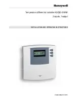
The Honeywell ASC02-01WM is an innovative and reliable device designed to enhance your home's comfort. With its user-friendly interface, it simplifies the installation and operation process. To access the comprehensive Installation and Operating Instructions Manual for free, download it from manualshive.com, ensuring seamless setup and optimal performance.
Page 2: ...2 EN2B 0365GE51 R0710 ...
Page 6: ......


