

AlarmNet CELL-ANT Indoor Fixed Length Antenna
Installation Guide
General
The Communication Module uses an internal dual band cellular antenna. In most cases, this antenna will provide a sufficient received signal
strength indication (RSSI) for a successful installation.
The Indoor Fixed Length Antenna should be used in installations where moving the antenna to a higher point within the building will provide
better RSSI.
Signal Strength
For reliable service, communication module should only be installed in locations where there is satisfactory signal strength. The signal strength
LED (green) lights steady to indicate satifasfactory signal strength. The signal strength value measured in dBm can be viewed on the 7720P
Programming Tool, by using the
shift <E>
command.
dBm is displayed as a negative value on the 7720P and a smaller negative number is better.
i.e., -60 dBm is a better signal strength than -100 dBm.
Installation Guidelines
Use these guidelines to maximize the performance of the module and simplify your installation.
•
Find the best coverage before mounting and wiring the radio by moving the module to several locations while monitoring the signal
strength.
•
The best signal strength can usually be found on an exterior wall at the highest point in the building. Avoid the basement.
•
Maintain at least 12 inches of clearance between the module and steel I-beams, HVAC ducts, metal studs, steel roofs or roofs,
exterior walls with metalized insulation or aluminum siding and other large metal objects.
If consistent signal strength cannot be found with the internal antenna, an external antenna should be used.
Indoor Antenna
The antenna is not weatherproof, and must be installed indoors and mounted vertically while maintaining 12 inches of clearance from large
metal objects. Install the antenna as follows:
1.
Measure and record the communication module signal strength using the internal antenna for reference.
2.
Disconnect all power from the unit, including the battery.
3.
Remove plastic plug from the SMA mounting hole on top of the communication module housing, and insert the SMA end of the
adapter cable.
4.
Secure the SMA connector with the included washer and nut.
5.
Plug the u.FL connector on the other end of the adapter cable into the external antenna port and route cable as shown.
6.
Find a suitable location that will allow the antenna to be mounted vertically.
7.
Route the antenna cable and connect the SMA to the module.
8.
Restore power to the unit, measure the signal strength and compare the new value to the value recorded in step 1.
9.
If needed, adjust the location of the antenna until the signal strength LED lights green.
10. Permanently mount the antenna vertically using the included hardware.
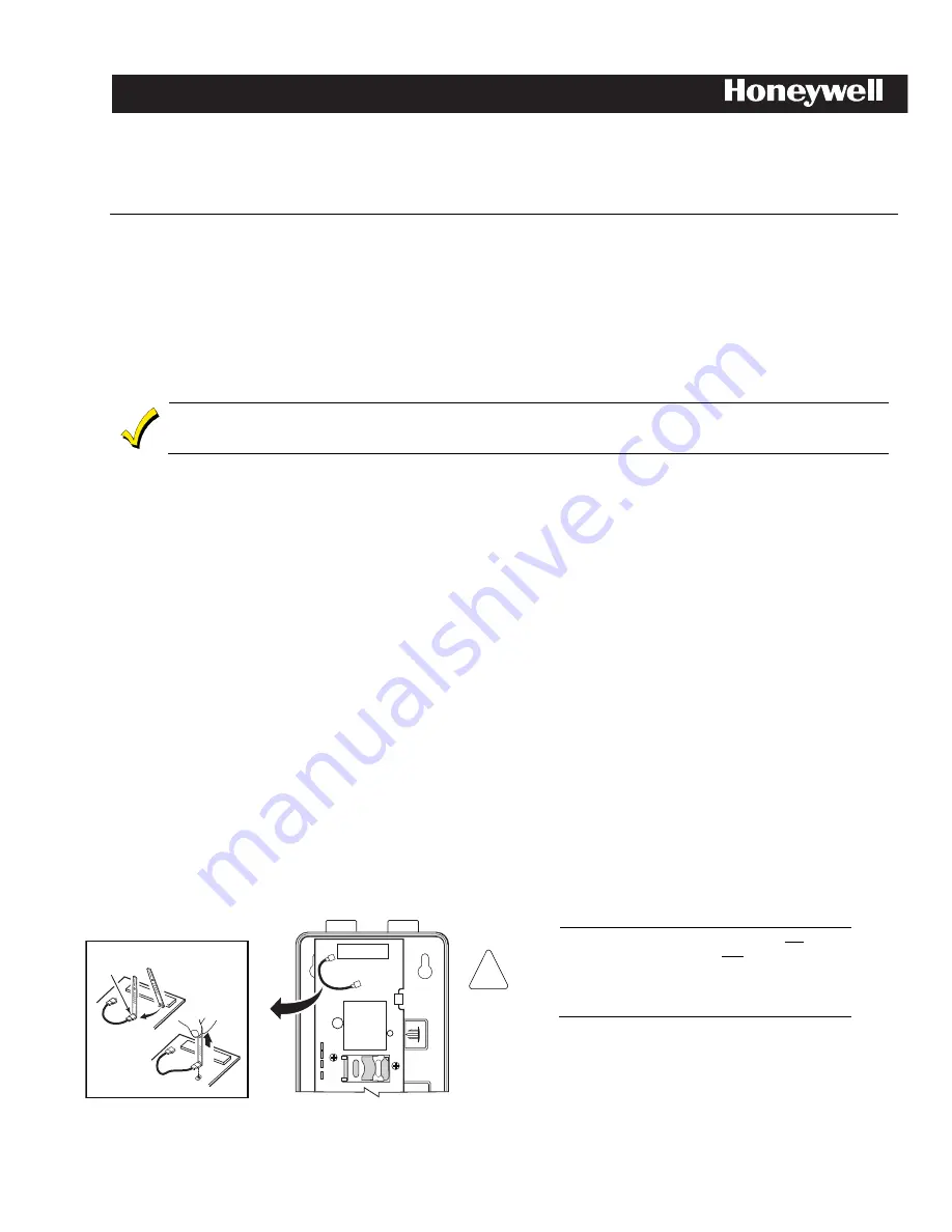
Antenna Cable Removal Tool
cell-ant3dB-002-V0
DETAIL A
2
ANTENNA
CABLE
REMOVAL
TOOL
SEE
DETAIL A
1
Insert tool
under RF
Connector
(not wire)
Pu
ll
u
p
3
1.
Slip the Antenna Cable Removal Tool (p/n 700-03513) under RF
Cable connector as shown.
!
PLEASE: (1) DO NOT use the tool to pry the
connector loose. Instead, pull directly upward,
perpendicular to the circuit board. Do not pull
on the cable. (2) USE CAUTION not to damage
the adjacent components when inserting the
Antenna Cable Removal Tool.
2.
Pull directly upwards until the connector detaches from the
module’s receptacle as shown in Detail A. (This cable is no
longer needed.)
3.
Repeat step 1 and 2 to disconnect the cable from the GSMX4G.
(This cable is no longer needed.)


