

ACU Wireless Analog Converter Unit – Quick Installation Guide
For Online Support visit: http://www.security.honeywell.com/hsc/resources/MyWebTech/
General Information
Power Transformer
This guide provides information on installing and setting up Honeywell's ACU Wireless
Analog Converter Unit (referred to as the ACU). The ACU allows any camera that outputs
NTSC video to be used with Honeywell's Total Connect Video services.
Some major features of Honeywell's ACU Wireless Analog Converter Unit are:
Wired or Wireless communications. Wireless communications utilize the 802.11b/g/n
protocol with WPS security. WPS (Wi-Fi Protected Setup) is a standard for easy setup of
a secure wireless network.
Has a video pass-through connection for a direct NTSC video feed to a local monitor.
Status LEDs, and 10/100 Mbps Ethernet port connectivity.
IMPORTANT: This device is for indoor use only. DO NOT mount this ACU within one [1]
foot of any wireless device.
To utilize the ACU, you must have:
An AlarmNet account for a GSM or Internet communicator, or a “Video Only” account.
Total Connect account. (If an account does not exist, the dealer should use the
AlarmNet Direct website to set up a Total Connect account for the customer.)
Internet access with a router capable of DHCP hosting. For wireless use, the router must
also support one button WPS data encryption. If this is not available, order the
Honeywell WAP Wireless Access Point for connection to your router.
PACKAGE CONTENTS
ACU Wireless Analog Converter Unit
Hardware Bag
(includes)
Mounting brackets [2] with screws [4]
Antennas [2]
GPIO Connector
Component Identification
75
POWER
NETWORK
ACTIVE
RESET
VIDEO
OUT
VIDEO
IN
OFF
LINE
OUT
LINE/MIC
IN
RESET and WPS switch –
Used to reset the
ACU to factory defaults and is also used to initiate
WPS for wireless security.
Reset – Ensure the POWER LED is on and not
blinking. Then use a paper clip to depress for
12-seconds. After the unit reboots, the
POWER LED will blink 3 times to confirm the
reset has completed.
WPS – Refer to the topic on Configuring
Wireless Security.
VIDEO OUT –
Pass through BNC connector.
Enables the NTSC video from the camera to be
fed to a local monitor. When a local monitor is
used, ensure the adjacent
75
Ω
OFF
switch is set
to the UP position.
VIDEO IN –
Attach the NTSC output from your
video camera here.
LINE OUT –
(Not used.)
LINE / MIC IN –
(Not used.)
NETWORK LED (green)
On – The LAN is detected and active.
Flashing – Data is being transferred via the
LAN.
ACTIVE LED (green)
Flashing – ACU camera is being viewed via the
internet.
Off – ACU camera is not being viewed via the
internet.
POWER LED (green)
On – Power is on.
Flashing – Will blink during initial power up
condition. This will take about 20-seconds.
antenna connector
– Orient the antennas vertically. Used for wireless connectivity
(Always use both antennas).
ETHERNET –
For connection to
any router (configured for DHCP), or Honeywell's
WAP Wireless Access Point
. Supports 10/100 Mbps.
(Using the Ethernet connector will disable the wireless communications.)
GPIO Connector –
(Not used.)
POWER –
Connection for the Power Transformer (12V/1A).
1. Mount and Wire the ACU
For most installations the ACU can simply be attached to a surface using high-strength hook & loop tape,
such as VELCRO ® (not supplied).
However for more permanent installations, the ACU comes with two "L" brackets and screws. These "L"
brackets attach to the sides of the ACU using the supplied machine screws. Then the ACU can be
fastened to the mounting surface by screwing through the "L" brackets using screws suitable for the
mounting surface.
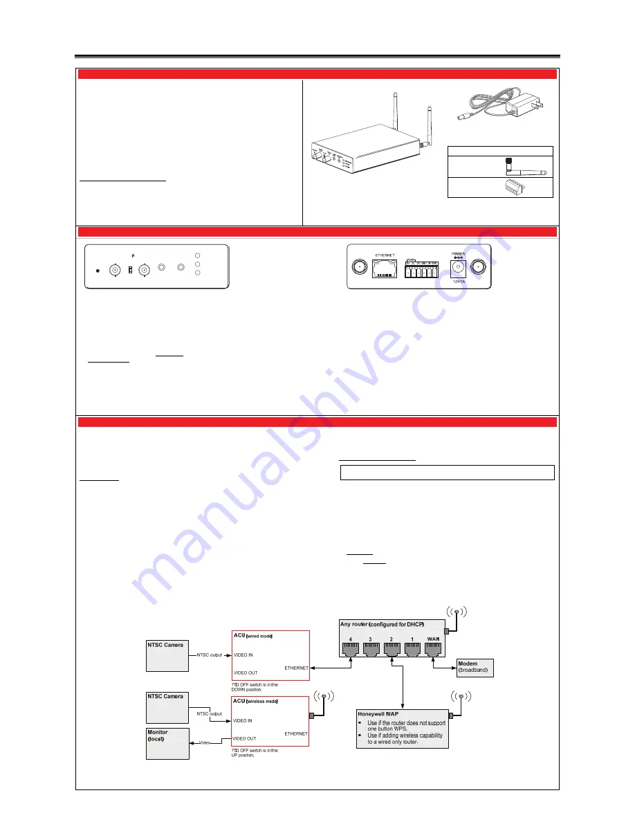
Wiring the ACU (
Refer to the diagram below, that shows typical ACU configurations.
)
NOTES:
For making video
connections
, use a 75 ohm cable such as RG-59 and the appropriate connectors.
E
nsure
the router is configured for DHCP. (This is the default setting for most routers.) You can access
the router's configuration page and enable DHCP (refer to the router's manual) if necessary.
1.
Connect the camera's NTSC video output to the VIDEO IN on the ACU.
2.
If a local monitor is to be used, connect the VIDEO OUT on the ACU to the video input on the monitor.
Ensure the
75
Ω
OFF
switch is in the UP position.
3.
For wired connectivity, connect the ACU to a router (configured for DHCP) port using an Ethernet
cable.
4.
For wireless connectivity, use any wireless router that supports one button WPS. If one button WPS is
not supported, connect the Honeywell WAP to the router.
Note that using the ACU’s Ethernet connector will disable the wireless communications. If wireless
communications is desired we suggest using the Ethernet connector for the initial setup.
Then when everything works, remove power from the ACU and remove the Ethernet cable. When the
ACU is powered up again it will be in the wireless mode.
5.
Connect the Power Transformer connector to the power connector on the ACU back.
6.
Secure cables and wires with cable ties as necessary.
7.
Plug the Power Transformer into a non-switchable power outlet. Wait for the POWER
indicator to light solid.
Configuring Wireless Security:
Note: If you are using a wireless router that supports WPS instead of the Honeywell
WAP, please refer to the manufacturer’s guide to setup wireless security.
When initially powered up, the ACU and WAP use the same default AES key (encryption
code). You should create a new AES key to ensure your wireless devices are associated
with your WAP. To create a new AES key, perform the steps below.
IMPORTANT - In the steps below, if not responding to the wireless configuration, please
initiate a Reset. U
se a paper clip to depress and hold the RESET switch for 12-seconds
and start over.
1.
Ensure an Ethernet cable is not connected to the ACU, then plug the Power
Transformer into an outlet. Wait for the Power indicator to light solid.
2.
Press and hold the RESET button on the WAP Wireless Access Point, for
3 seconds
, then RELEASE.
3.
Within
1
minute
, using a paper clip, click and RELEASE the RESET button on the
ACU
.
4.
Allow up to 45 seconds for the WPS to complete, then verify successful wireless
security as indicated by a STEADY GREEN Power LED and a Network LED that
occasionally BLINKS GREEN. If these indicators are present you are done.
5.
Repeat the steps above for each ACU.


