K5320V2 4/04 Rev. A
ADEMCO 6148
Remote Keypad
INSTALLATION AND SETUP GUIDE
GENERAL INFORMATION
The ADEMCO 6148 is an addressable remote keypad
designed for use with ADEMCO control panels. Addresses
are set via the keypad keys.
The keys on the keypads are continuously backlit for
convenience.
KEYPAD DISPLAY AND LEDS
The ADEMCO 6148 keypad has a fixed-word display and a 2-
digit zone identifier.
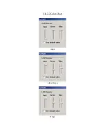
The following table describes the LEDs and their functions:
LED Function
Red (ARMED)
Lights when the system is armed in any mode.
Green (READY)
Lights when the system is "ready" to be armed.
SPECIAL-FUNCTION KEY PAIRS
The keypad also features special-function key pairs. These
key pairs may be used to activate panic alarms. See the
control's instructions for details.
Key pairs activate immediately.
The following key pairs are used by the ADEMCO 6148 to
manually activate silent emergency, audible emergency,
personal emergency, or fire alarms:
•
[1] & [
✱
]
•
[
✱
] & [#]
•
[3] & [#]
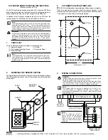
WIRING AND INSTALLATION
The keypads can be surface mounted directly to a wall, or to
a single- or double-gang electrical box.
1.
Remove the case back
by pushing down two "snaps."
See diagram that follows.
2.
Route wiring from the control panel
through the
opening in the case back.
3.
Mount the case back
to a wall or electrical box.
4.
Wire directly from the keypad’s terminal block
to
the terminal block on the control board. See Wirng
Table that follows.
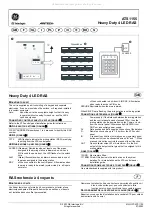
Wiring Table
Keypad
Control Panel
Wire Color
Î
G
Data In
Green
–
– Aux Pwr (GND)
Black
+
+ Aux. Pwr
Red
Ï
Y
Data Out
Yellow
5.
Reattach the keypad
to its case back.
RETAINING
SNAPS
NOTE:
TO REMOVE CASE BACK
PUSH IN THE TWO MOUNTING
SNAPS LOCATED ALONG THE
BOTTOM OF THE KEYPAD
AND LIFT UP.
6148-005-V1
SETTING THE KEYPAD ADDRESS
The keypad can be set either for an address of 00-30, or to the
non-addressable mode (31). The keypad's default address is 31.
Refer to the Installation and Setup Guide of the
control panel being used for correct address
settings and other details.
To change the keypad's address, do the following:
1. Power up the keypad. Within 60 seconds of power-up, press
and hold down the [1] and [3] keys at the same time for 3
seconds. (If unable to enter address mode, power up and try
again.)
The current keypad address is displayed, and the cursor is
under the "tens" digit. If 10 seconds have passed with no
key entry, the keypad automatically exits address mode.
You must power down, power up and start address mode
again.
NOTE
: The keypad will not enter address mode if the panel
to which it is connected is in programming mode.
2. Set the current address to "00": Press [0] to clear the
current "tens" digit. The cursor moves to the "ones" digit
position. Press [0] to clear the current "ones" digit. The
cursor moves back to the "tens" digit position.
3. Enter the keypad's address: Enter the proper "tens" digit of
the keypad's address. The cursor moves to the "ones" digit
position. Enter the proper "ones" digit of the keypad's
address. Note that address "31" sets the keypad to non-
addressable mode.
4. Exit address mode: Press [
✱
] to save the displayed address
and exit address mode.
VIEWING THE KEYPAD ADDRESS
Press and hold down the [1] and [3] keys at the same time for
about 3 seconds. The current address is displayed. No key
entry is allowed. Press any key to exit, or wait 10 seconds to
automatically exit viewing mode.