HW-500-003
1
I56-3934-002R
INSTALLATION AND MAINTENANCE INSTRUCTIONS
Models: 5193SD, 5193SDT
Addressable Photoelectric Smoke Detector
BEFORE INSTALLING
Before installing detectors, please thoroughly read the supporting
Honeywell control panel installation instructions, which provide de-
tailed information on detector spacing, placement, zones, and special
applications. Copies of the installation instructions are available from
Honeywell. NFPA 72 and NEMA guidelines should also be observed.
NOTICE
:
This manual shall be left with the owner/user of this equipment.
IMPORTANT
:
This detector must be tested and maintained regularly follow-
ing NFPA 72 requirements. At a minimum, cleaning should be performed an-
nually.
GENERAL DESCRIPTION
The Model 5193SD/SDT addressable photoelectric smoke detector incorpo-
rates a state-of-the-art optical sensing chamber and an advanced microproces-
sor. Built-in Drift Compensation algorithms automatically maintain proper
operation at factory calibrated detection levels, even when sensitivity is al-
tered due to the presence of contaminates settling into the unit’s chamber. In
order for this feature to work properly, the chamber must never be opened
while power is applied to the smoke detector. This includes cleaning, mainte-
nance or screen replacement. Should it become necessary, the screen/sensing
chamber is field replaceable. Once the detector has reached its limit of com-
pensation, a maintenance signal is indicated at the panel. The 5193SDT also
features a restorable, built-in, fixed temperature (135°F) thermal detector.
The detector is designed to provide open area protection and to be used with
compatible UL-listed Honeywell control panels.
Installation of the 5193SD/SDT detector is simplified by the use of a mounting
base that may be pre-wired to the system, allowing the detector to be easily
installed or removed.
Two LEDs on the detector provide a local visual indication of the detector’s
status:
TABLE 1: DETECTOR LED MODES
Green LED
Red LED
Power-up
Blink 10 sec
Blink 10 sec
Normal (standby)
Blink 5 sec
—
Out of sensitivity
Off
Blink 5 sec
Heat Sensor Trouble Off
Blink 10 sec
S m o k e / T h e r m a l
Alarm
Off
Solid-(Initiating
device only)
Blink 1 sec
During initial power-up, the red and green LEDs will blink synchronously
once every ten seconds. It will take approximately 50 seconds for the detector
to finish the power-up cycle (see Table 2).
TABLE 2: POWER-UP SEQUENCE FOR LED STATUS INDICATION
Condition
Duration
Initial LED Status Indication
approx.14seconds
Initial LED Status Indication
(if excessive electrical noise is present)
4 minutes
NOTE
:
If, during power-up, the detector determines there is excessive electri-
cal noise in the system such as those caused by improper grounding of the
system or the conduit, both LEDs will blink for up to 4 minutes before display-
ing detector status (see Table 2).
After power-up has completed and the detector is functioning normally within
its listed sensitivity range, the green LED blinks once every five seconds. If the
detector is in need of maintenance because its sensitivity has shifted outside
the listed limits, the red LED blinks once every five seconds. When the detec-
tor reports an alarm condition to the control panel, the panel will send a code
command to steadily light that unit’s red LED. If the same loop has multiple
detectors reporting alarm, only the first detector that reported alarm would
have have its red LED turned on steadily. The remaining units in alarm
will blink their red LED once per second. However, the panel will latch the
address of all detectors that reported alarm. The LED indication must not be
used in lieu of the tests specified under
Testing
.
To measure the detector’s sensitivity, the Model SENS-RDR Infrared Sensitivity
Reader tool (see Figure 5) should be used.
PROGRAMMING
The 5193SD/SDT has an internal serial number which must be enrolled in the
control panel prior to its use in the system. Before programming, make sure
the detector is mounted on its base. To program this device, enter the control
panel’s Zone Programming mode. Assign the appropriate Fire Zone Type and
an Input Type of “06” (serial number polling loop device). When prompted,
either press the “test” button on the smoke detector to enroll the serial num-
ber (it will be displayed on the keypad), or enter the serial number manually
through the keypad. Press the “test” button again to enroll the loop number,
or enter loop number “1.”
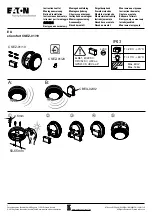
MOUNTING
Each 5193SD/SDT detector is supplied with a mounting base that can be
mounted:
1. Direct mount or to ceiling using drywall fasteners (Figure 1).
2. To a single gang box, or
3. To a 3
1
/
2
-inch or 4-inch octagonal box, or
4. To a 4-inch square box with a plaster ring
I
56-3934-00
2R
SPECIFICATIONS
5193SD, 5193SDT
Heat Sensor: (Model 5193SDT):
135°F (57.2°C); Fixed Temperature Electronic Thermistors
Operating Ambient Temperature Range: 32 to 100°F (0 to 38°C)
Operating Humidity Range:
0 to 95% RH non-condensing
Storage Temperature Range:
–4 to 158°F (–20 to 70°C)
Diameter (including base):
5.3 inches
Height (including base):
2.0 inches
Weight:
6.3 oz.
Agency Listing:
UL-268
System Voltage Range:
7-14V
Standby Current (maximum @ 12V)
LED off:
1.2mA
LED on:
2.8mA