
S
CW
DL
READ IT
OR
WATCH IT
Read instructions or watch easy-to-follow video.
Scan QR code or visit bit.ly/2FAzqcD
45366 (12IN.), 45367 (18IN.), 45368 (24IN.),
45369 (36IN.), 45370 (48IN.)
DIRECT WIRE
LED LIGHT FIXTURE
SAVE THESE INSTRUCTIONS IN A LOCATION CLOSE TO YOUR CABINET
SO YOU CAN REFER TO THEM AT A LATER TIME.
CAUTION: DO NOT USE POWER TOOLS TO SECURE SCREWS, AS
THERE IS A RISK OF STRIPPING THE SCREWS.
DO NOT USE WITH A DIMMING CIRCUIT OR ANY OTHER
ELECTRONICALLY SWITCHED CONTROL.
DO NOT EXCEED THE MAXIMUM CONNECTED UNITS INDICATED ON
THE POWER ADAPTER/LED DRIVER.
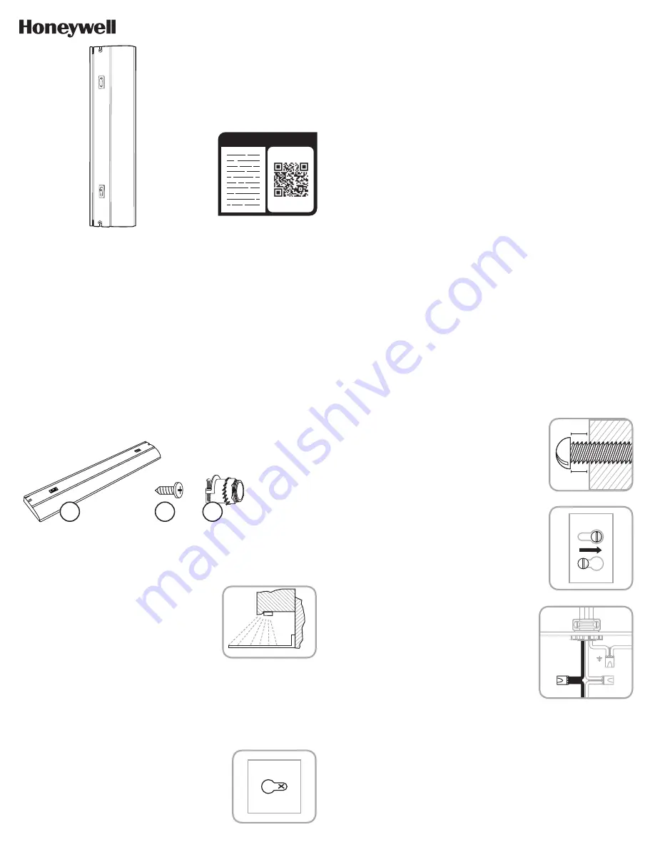
PACKAGE CONTENTS
INSTALLATION PROCEDURE FOR DIRECT
WIRE LIGHT FIXTURE
Note:
For kitchen installations, the recommended mounting for the
dimmable LED light fixture is near the front lip of your under cabinets as
shown in the illustration (
see Figure 1
). The LEDs will face the front of
the cabinet. This provides the best light distribution across a countertop.
1. Consult a local licensed electrician or electrical
contractor if you are not sure about the installation.
2. Ensure that electricity is TURNED OFF at the main
circuit breaker or fuse box. DO NOT ATTEMPT TO
INSTALL FIXTURE WITH THE POWER ON.
3. Select a suitable dry mounting location (for indoor
use only). Make sure the mounting surface is capable of
supporting the fixture.
4. Remove the lens/diffuser by lightly pulling the rear edge
toward the front and upward. The lens/diffuser should
pop out easily.
5. Remove the cover/housing by unscrewing the screws
located on the top of the cover. Firmly push forward on
the bottom front of the housing to unlatch it from the
catch points. The hardware kit is inside the wiring cavity.
6. Ensure that there is adequate space to install the
fixture by using the base as a mounting template. While
the base is held in place, mark location for pilot holes
(
see Figure 2
).
7. Choose a suitable knock-out location from those
provided on the fixture. Remove the knock-out with
a screwdriver (not included).
FIGURE 1
CABINET
COUNTER TOP
W
ALL
SW
CW
DL
A
B
C
A.
Light Fixture x1
B.
M4 x 12mm short mounting
screw x2
C.
Strain relief assembly x1
8. Remove the nut and lock washer and insert the threaded
end of the strain relief (provided in the installation kit)
into the selected opening on the fixture. Secure the
strain relief by tightening the nut and lock washer. The
nut and lock washer should be tightened with a tool
such as a pair of pliers to ensure the strain relief is
properly grounded to the fixture.
9. It is recommended that a pilot hole be drilled in the
mounting surface for wood screws. Pre-drill holes in
the mounting surface with a 1/16in. (1.5 mm) drill
bit for softwoods and a 3/32in. (2.4 mm) drill bit
for hardwoods.
10. Drive the screws provided in the mounting hardware into
the mounting surface until approximately 1/8in.
(3.1mm) of space remains under the head of the screw
(
see Figure 3
).
11. Align the keyholes in the fixture with the two screws and
slide into place (
see Figure 4
).
12. Tighten screws to secure fixture.
13. For ease of installation, the top cover can be hung on
the base, which is already attached to the cabinet, using
the built-in hanging flanges.
14. Install the armored cable to meet electrical codes.
Tighten the two screws on the strain relief connector to
secure the cable.
15. Connect the hot (black) AC supply wire to the hot (black) wire
of the fixture. Secure the connection with the wire nuts
provided (
see Figure 5
). Pull wires to check for tightness.
16. Connect the neutral (white) AC supply wire to the neutral
(white) wire of the fixture. Secure the connection with the
wire quick connects provided (
see Figure 5
). Pull wires to
check for tightness.
17. Connect the ground (green or bare copper) AC supply wire to
the green or bare copper ground (green or bare copper)
wire of the fixture. Secure the connection with the wire
quick connects provided (
see Figure 5
). Pull wires to
check for tightness. If your electrical system contains no
grounding wire, you should consult a qualified electrician
before proceeding with the installation.
18. Ensure that no bare wires are exposed after making the
electrical connections.
19. Arrange the wires inside the fixture and reattach the cover/
housing by reversing the removal instructions. Ensure all
the wires and connections are sealed properly inside the
fixture without pinching any wires. Ensure the top cover
screws and washers are secure.
20. Reinsert lens.
21. Turn on the electricity at the circuit breaker or fuse box.
DIMMABLE FUNCTIONALITY
1. For use of dimming function, please use a compatible LED dimmer.
2. Follow dimmer setup instructions for optimal performance.
SELECTING COLOR TEMPERATURE
This Honeywell LED light fixture allows you to select from a warm white
light (2700K), cool white light (4000K) or daylight setting (5000K). To
select your desired CCT, simply use the 3-position switch: WW (Warm
White) CW (Cool White) or DL (Daylight). Please note that the switch
only controls the color temperature for a single fixture. It does not control
other connected fixtures.
FIGURE 3
1/8IN.
3.1MM
FIGURE 4
FIGURE 5
INSERT
SLIDE
FIGURE 2
1/16IN. (1.58MM)


