

® U.S. Registered Trademark
Copyright © 2003 Honeywell International Inc. •
• All Rights Reserved
INSTALLATION INSTRUCTIONS
69-1372-1
32003487-001
Fan Timer
APPLICATION
The 32003487-001 Fan Timer is used to remotely control
Honeywell heat and energy recovery ventilators. The
timer changes the ventilator to high speed for increased
circulation and comfort. Touching the time control pad
selects a ventilator high-speed run time of 20 minutes.
Up to ten timers can be installed to one ventilator for
added user convenience. Installation is quick with the
Decora™ Switch Plate and the timer mounts in a full or
one-half depth electrical box. The illuminated display
shows timer status.
INSTALLATION
When Installing This Product...
1.
Read these instructions carefully. Failure to follow
them could damage the product or cause a hazard-
ous condition.
2.
Check the ratings in the instructions and on the
product to make sure the product is suitable for
your application.
3.
Installer must be a trained, experienced service
technician.
4.
After installation is complete, check out product
operation as provided in these instructions.
CAUTION
Electrical Hazard.
Can cause personal injury or equipment dam-
age.
Disconnect power supply before installation.
Be sure ventilator low voltage control circuit is
disconnected from external power sources.
Wiring and Mounting
All wiring must comply with local electrical codes and
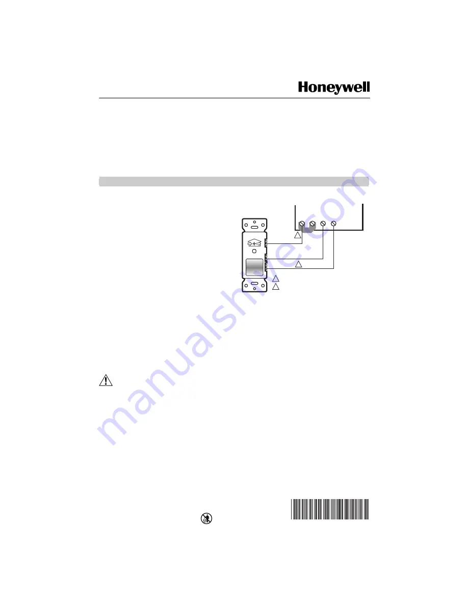
ordinances. Refer to Fig. 1 for typical hookup.
Fig. 1. Typical hookup of fan timer to
heat recovery ventilator.
1.
Connect the wires to the correct screw terminals as
shown in Fig. 1.
2.
Align the timer mounting holes over the electrical
box mounting holes.
3.
Insert and tighten the two mounting screws.
4.
Place the Decora™ Switch Plate over the timer.
Insert and tighten the switch plate mounting
screws.
Setting and Display Status
1.
Press timer control pad to set the timer to 20 min-
utes. See Fig. 2. Pressing the control pad again,
before the 20 minutes end, resets the timer to 20
minutes.
2.
Observe that the timer indicator illuminates when
the timer is activated and remains on for the cycle
duration. See Fig. 2 and Table 1.
IMPORTANT
When more than one timer is installed, pressing
the control pad on any timer resets the ventilator
override time to 20 minutes. The indicators on
all timers will remain illuminated for the cycle
duration.
M14410A
1
2
DO NOT REMOVE JUMPER.
MAXIMUM WIRE LENGTH IS 100 FEET (30 METERS).
USE 20 GAUGE WIRE.
1
2
ST2
RED
BLACK
GREEN
ST3
ST1
ST4


