background image

This manual covers a range of
conventional fire panel and include
system design, installation and
configuration information.

The fire panels covered are
designed in accordance with the
requirements of EN54 Part 2:1997
+ AMD 1 (and include optional
clauses 7.8, 7.10 & 7.11), plus the
requirements of EN54 Part 4:1997
+ AMD 1 and AMD 2.
This publication covers the
Conventional  fire alarm panels:

q

1 zone panel:-  13270-01LB and
75585-01NMB

q

2 zone panel:-  13270-02LB and
75585-02NMB

q

4 zone panel:-  13270-04LB and
75585-04NMB

q

8 zone panel:-  13270-08LB and
75585-08NMB

q

Fire alarm repeat panel:
13271-08LB and 75586-08NMB.

The panels are supplied without
batteries.

This manual is intended
for use by installers and
commissioning engineers.

A separate Operating
instructions and Log book
has been supplied along
with this booklet which
must be forwarded on to
the End User.

4188-424 issue 4_Part 1_10-09

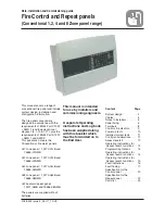
Data, Installation and Commissioning guide

Fire Control and Repeat panels

(Conventional 1, 2, 4 and 8 Zone panel range)

Content

Page

System design ·  · .  .  .  .  . 2
Cables - ·  ·  ·  ·  · .  .  .  .  . 4
Notes to installers .  .  .  .  . 5
Panel fixing·  ·  ·  · .  .  .  .  . 6
Terminals ·  ·  ·  · .  .  .  .  . 8
Controls & indicators .  .  .  . 9
Power up tests ·  · .  .  .  .  . 10
Installed system tests .  .  . 11
Config. considerations .  .  . 11
Access levels 2 · .  .  .  .  . 12
Operating instructions for

Access level 2 functions .  . 12

Programming Options .  .  . 14
Operating instructions for

Access level 3 functions .  . 14

Operating instructions for

Access level 4 functions .  . 15

Fault indications · .  .  .  .  . 16
Fault finding ·  ·  · .  .  .  .  . 17
Specification for the
Control panel·  ·  · .  .  .  .  . 20
Specification for the
Repeat panel·  ·  · .  .  .  .  . 22
Parts list ·  ·  ·  ·  · .  .  .  .  . 23

Summary of Contents for 13270-01LB

Page 1: ...al is intended for use by installers and commissioning engineers A separate Operating instructions and Log book has been supplied along with this booklet which must be forwarded on to the End User 4188 424 issue 4_Part 1_10 09 Data Installation and Commissioning guide Fire Control and Repeat panels Conventional 1 2 4 and 8 Zone panel range Content Page System design 2 Cables 4 Notes to installers ...

Page 2: ... All manual call points used must have a 470 ohms series resistor Where a zone circuit is not being used the end of line capacitor unit or bipolar capacitor must be fitted across its terminals in the panel System design Fire Panels 2 4188 424 issue 4_Part 1_10 09 Un used Zone circuits must be terminated with an end of line Capacitor unit or bipolar capacitor End of line Capacitor unit or bipolar c...

Page 3: ...schools and colleges Auxiliary Contacts These are normally open NO and normally closed NC contacts that change over when the panel goes into a fire condition The contacts are rated at 24V dc 1A for a resistive load and should not be used to switch voltages in excess of 50V The auxiliary circuits should be powered from an independent power supply NOTE There is no indication given at the panel of cl...

Page 4: ... and Relay shown connected here are typical examples of external circuit Figure 6 Fire fault 24V outputs Length per circuit Type of circuit Recommended cables also see BS5839 Part 1 guidance 2m Mains power supply cord see power supply cord 1Km Zone circuit See BS5839 Part 1 2002 A2 2008 for guidance 1Km Sounder circuits 100m Auxiliary circuit 100m Common fire and fault circuit 100m Class change ci...

Page 5: ... the installers responsibility to provide adequate fixtures and fittings for the type of construction surface onto which a product is to be installed as an aid to this decision the weight and overall size of each full assembly together with implications on cable entries and routing should be taken into consideration NOTE All these procedures assume that the cable gland steel box BESA box and other...

Page 6: ...em wiring can be tested whilst not connected to the respective terminals at each system device CAUTION DO NOT undertake high voltage insulation tests WITH THE CABLES CONNECTED to their terminals This may damage the electronic circuitry in the product I Refit the front panel including the electronic assembly into the panel using four M3 screws and connect the transformer cable and earth cable see F...

Page 7: ...Transformer Earth T1A T1B E Panel Backbox Transformer cables to electronic assembly Earth connection to the electronic assembly ve ve Bottom Plate instructions printed onto plate Ribs NOTE The metal plates are to be located under the ribs on the front panel and fixed in place using M3 screws Figure 10 Refitting electronic assembly 378mm wide 245mm high 60mm deep cross section of the wall to which ...

Page 8: ...750mA Fuse 1 Zone panel 2 Zone panel 4 Zone panel 8 Zone panel Repeat panel SECTOR 1 SECTOR 2 SECTOR 3 SECTOR 4 SECTOR 5 SECTOR 6 SECTOR 7 SECTOR 8 BATTERIES 24V 1 8 All other fuses ie FS1 FS2 and FS11 are 20mm x 5mm diameter QB Quick Blow AS Anti Surge Fuses T1A T1B E CFR 24 CFT 0 CC1 CC2 R R NC NC NO NO Zn Zn To Zone and Sounder Circuits where n signifies circuit number 1 to 8 Sn Sn Auxiliary co...

Page 9: ...is flashing A lit zone yellow indicator along with the Disabled indicator is used to show a disabled zone q System Fault This indicator when lit indicates that there is a fault in the panel s processor q Power Fault When lit or flashing indicates that there is a power supply fault present q Earth Fault This indicator when lit or flashing indicates that there is an Earth Fault on the system q Sound...

Page 10: ...r or manual call point on a zone circuit b Connect the zone cable to the zone circuit terminals c Carry out zone open circuit and short circuit tests and check appropriate indications are given d Repeat the above for other zone circuits Sounder circuit tests a Transfer the end of line resistor unit to the last device on a sounder circuit b Connect the sounder circuit cable to the sounder circuit t...

Page 11: ... a Fire indication is given for 10 seconds duration followed by a system reset Table 2 Test mode operation Config considerations Repeat panel config q The power up procedure for the repeat panel is the same as the main panel q The presence of a repeat panel needs to be set up at the main panel see Config and Test section Delay mode In the Delay mode there is a delay between detecting a fire and so...

Page 12: ...eck that the Test indicator is On and the zone fault indicator is lit The zone can be tested without an alarm of fire How to set the panel to operate in Test mode B q Enter the AL2 access code and check that the Access function lamp is lit q Press the shift and 4 buttons followed by the number of the zone to be placed in test mode Check that the Test indicator is On and the zone fault indicator is...

Page 13: ...n lamp is lit q Press the shift and 9001 buttons in sequence and check that the System LED is flashing q Input the new AL2 access code How to change AL3 password q Enter the AL3 access code and check that the Access function lamp is lit q Press the shift and 9002 buttons in sequence and check that the System LED is flashing q Input the new AL3 access code How to set and unset the Delay mode q Ente...

Page 14: ...vel 2 q Enter 3 digit AL3 access code default 321 Press Shift Enter data 9000 000 001 To allow Display test at access level 1 q Enter 3 digit AL3 access code default 321 Press Shift Enter data 9000 001 001 To allow Display test at access level 2 default setting q Enter 3 digit AL3 access code default 321 Press Shift Enter data 9000 001 002 To allow Test condition at access level 2 default setting ...

Page 15: ... silence alarms before reset q Enter 4 digit AL4 access code 7426 Press Shift Enter data 9000 033 followed by 000 for a Reset Silences and 001 for UK Linking How to set Sound Resound alarms configuration default is sound alarms at any time q Enter 4 digit AL4 access code 7426 Press Shift Enter data 9000 034 followed by 000 for a Sound Alarms at any time and 001 for Resound only How to set Zone sho...

Page 16: ...fault A zone fault occurs when a zone circuit cable is open circuit or short circuit or the end of line capacitor unit has been disconnected or a detector has been removed What is a Sounder fault A sounder fault occurs when a sounder circuit cable is open circuit or short circuit or the end of line resistor unit has been disconnected What is a Mains power fault A mains failure occurs when the main...

Page 17: ...shing Yes Are the Fault and Zone Fault indicators flashing Yes Are the Fault and Access Function indicators pulsing Yes Are the Fault and System Fault indicators On and is the Power On indicator Onor flashing Yes Are the Zone Fault and Disabled indicators lit Are the Sounder Fault and Disabled indicators lit Refer to Specialist help Yes Yes Refer to the Test mode see Page 11 18 18 Refer to the PSU...

Page 18: ...ry fault Charger fault at Main Panel Steady Steady Auxiliary supply sounder output supply fault at Main Panel Slow Flash Slow Flash Mains failed at Repeat Panel Slow Flash Fast Flash Battery disconnected Battery fault Charger fault at Repeat Panel If Access Function indicator flashes slowly there is a comms fault between the Main Panel and the Repeat Panel NOTE If there is a PSU fault at the Main ...

Page 19: ...slowly Normal Deactive Deactive Disable zone On On On Normal Active Deactive Disable Sounder On On On Normal Active Deactive Visual indications Audible indication Signals out Condition Fault Yellow Power Green Access Function Yellow Buzzer Aux Relay contacts Normally de energised Common fault Normally active Common fire Normally deactive Repeat Panel Link Fault Steady On Pulse slowly Pulse slowly ...

Page 20: ...uct family standard Immunity requirements for components of fire intruder and social alarm systems IP rating BS5490 IP31 indoor Knock In cable entry points 13 top 13 back Terminal size 2 5mm2 maximum Battery standby with 1mA load per zone and 1A total sounder alarm load 72hr standby plus 0 5hr with alarm load Auxiliary contacts operates with fire Pair of normally closed NC and a pair of normally o...

Page 21: ... power 60W 8 zone panel Internal supply 24V supply Feeds current limited zone circuit 24V fused output 24V dc 2V 2V or 24V 2V 4V battery operation current limited 5 ripple voltage 24V Sounder supply Feeds fused sounder circuit 24V dc 2V 2V 24V 2V 4V battery operation Current limited 5 ripple voltage Battery Charger Float voltage 27 3V 1 1 20degC Compensation 36mV K nominal Current limited 400mA 20...

Page 22: ...ck In cable entry points Top back entries Terminal size 2 5mm2 maximum Battery supply sealed lead acid 2 off12V 2 1Ah 3 4Ah See applicable batteries as listed for Control panel Standby duration 72hr standby User access By means of code entry via numeric key pad AL1 Authorised user No code is required AL2 Site security 3 digit code 123 AL3 Site engineering 3 digit code 321 AL4 Engineers 4 digit cod...

Page 23: ... call points MCP Part number Description 14112 08EN MCP Surface Red 470R 14112 48EN MCP Surface Red 470R c w cover 14112 19EN MCP Surface water resistant kit 14115 08 Keyswitch red surface 470R 14112 09NM Pack of 10 glasses Part number Description 71150 52NMA EN MCP Surface c w backbox EN54 version 470R 71150 55NMA EN MCP Surface with Cover and backbox EN54 version 470R 14115 08 Key Operated surfa...

Page 24: ...ntent hereof without obligation to notify any person of such revisions of changes Hamilton Industrial Park Waterside Road Leicester LE5 1TN UK Website www gent co uk Telephone 44 0 116 246 2000 Tech Support www gentexpert co uk Fax UK 44 0 116 246 2300 4188 424 issue 4_Part 1_10 09 by Honeywell Do not dispose of with your normal household waste Do not burn WEEE Directive At the end of their useful...

Reviews: