Honeywell 041450.17, Mounting And Operating Instructions
The Honeywell 041450.17 is a state-of-the-art device, designed to simplify your life. To ensure smooth installation and operation, make use of our comprehensive Mounting and Operating Instructions manual. Download it for free from manualshive.com, and unlock the full potential of your Honeywell 041450.17 with ease.
Share
Download


Reviews:
No comments
Related manuals for 041450.17
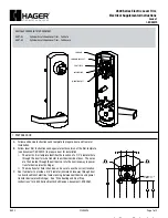
4500 Series
Brand: hager Pages: 3
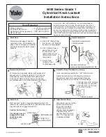
5400 Series
Brand: Yale Pages: 2
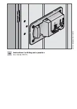
HST-FS
Brand: 4Ddoors Pages: 11
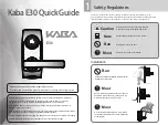
E30
Brand: Kaba Pages: 4

125
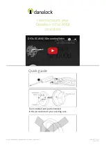
Brand: danalock Pages: 4

125
Brand: danalock Pages: 32

L701
Brand: Waferlock Pages: 3
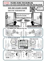
SHS-3321
Brand: Samsung Pages: 2
shs-h705
Brand: Samsung Pages: 2

TOUCH
Brand: Wattle Pages: 40
V3 SCANDI
Brand: danalock Pages: 8

V3 SCANDI
Brand: danalock Pages: 24

V3 EURO
Brand: danalock Pages: 32
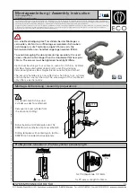
D-110
Brand: Eco Pages: 4
Contemporary Series
Brand: Gainsborough Pages: 2
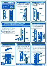
SD8
Brand: Gainsborough Pages: 2
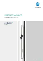
INSTINCT
Brand: Maco Pages: 35
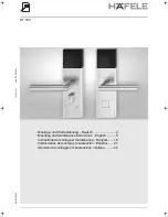
DT 700
Brand: Hafele Pages: 16


