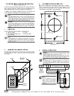
Honeywell 026421.10, Mounting And Operating Instructions
The Honeywell 026421.10 user manual provides essential Mounting and Operating Instructions for effortless setup and operation. This comprehensive manual is available for free download at manualshive.com, so you can conveniently access all the information required for maximizing the performance and functionality of your Honeywell 026421.10 product.
Share
Download


Reviews:
No comments
Related manuals for 026421.10
816
Brand: IDS Pages: 64
NetworX Series
Brand: GE Pages: 24
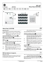
Interlogix Aritech ATS1155
Brand: GE Pages: 2

KTD-404
Brand: KALATEL Pages: 8
NX-148E - Security NetworX LCD Keypad
Brand: GE Pages: 24
OfficeServ ITP-5121D
Brand: Samsung Pages: 2

DS 5000 Series
Brand: Samsung Pages: 91

DS 5007S KEYSET
Brand: Samsung Pages: 20
OfficeServ 7200
Brand: Samsung Pages: 43

SPCK420
Brand: Vanderbilt Pages: 11
SCF SERIES
Brand: AC Tech Pages: 2

09 Series
Brand: eao Pages: 19
CK2.2
Brand: B&K Pages: 6

CK2.2
Brand: B&K Pages: 12

CK1.1
Brand: B&K Pages: 2
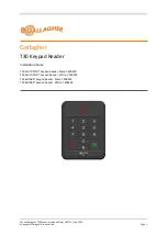
T30
Brand: Gallagher Pages: 13
System 236i
Brand: C&K systems Pages: 40
NX148-E
Brand: CADDX Pages: 16


