background image

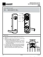
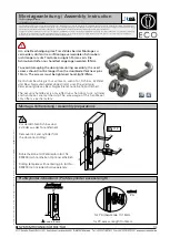
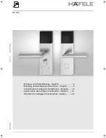
Montage-Anschluss-Anleitung

Elektromechanisches Sperrelement 3
Art.-Nr. 019032

Inhalt:

Seite

1. Allgemeines . . . . . . . . . . . . . . . . . . . . . . . . . 2

2. Funktionsbeschreibung . . . . . . . . . . . . . . . . 2

3. Montagehinweise . . . . . . . . . . . . . . . . . . . . . 4

3.1 Maßzeichnung . . . . . . . . . . . . . . . . . . . 4
3.2 Einbaurichtlinien . . . . . . . . . . . . . . . . . . 5
3.3 Einbauhilfe zur Positionierung

Bolzen-Gegenstücks . . . . . . . . . . . 7

4. Ansteuerungsmöglichkeiten . . . . . . . . . . . . . 8

5. Anschlussplan . . . . . . . . . . . . . . . . . . . . . . . 9

6. Ansteuerung mehrerer Sperrelemente . . . . 10

7. Notentriegelung . . . . . . . . . . . . . . . . . . . . . 10

7.1 Elektrische Notentriegelung . . . . . . . . 10
7.2 Mechanische Notentriegelung . . . . . . 10

8. Technische Daten . . . . . . . . . . . . . . . . . . . . 11

9. Zubehör . . . . . . . . . . . . . . . . . . . . . . . . . . . 12

des

P00731-10-002-08

2008-08-13

G104003 (EMA)
Z104003 (ZKA)

Änderungen

vorbehalten

D

GB

Ihr Partner in allen

Sicherheitsfragen

Internet: www.igs-hagen.de
Email:  [email protected]

Tel.:  +49  (0)2331  9787-0
Fax: +49 (0)2331 9787-87

IGS

IGS -
Industrielle Gefahren-
meldesysteme GmbH

Hördenstraße 2
58135  Hagen

Technology for life safety and security

Summary of Contents for 019032

Page 1: ...9 6 Ansteuerung mehrerer Sperrelemente 10 7 Notentriegelung 10 7 1 Elektrische Notentriegelung 10 7 2 Mechanische Notentriegelung 10 8 Technische Daten 11 9 Zubehör 12 des P00731 10 002 08 2008 08 13 G104003 EMA Z104003 ZKA Änderungen vorbehalten D GB Ihr Partner in allen Sicherheitsfragen Internet www igs hagen de Email info igs hagen de Tel 49 0 2331 9787 0 Fax 49 0 2331 9787 87 IGS IGS Industri...

Page 2: ...s Zutrittskontrollstellglied 2 Funktionsbeschreibung 2 1 Grundfunktionen Beim Anlegen der Betriebsspannung wird der Verschlussbolzen grundsätzlich zurück gefahren was der Stellung Zugang erlaubt AUF entspricht Durch eine Betriebsspannungs Unterbrechertaste könnte so eine einfache elektrische Notentriegelung verwirklicht werden Mit dem statischen oder dynamischen Steuersignal ZU wird der Verschluss...

Page 3: ...iebsspannungs Unterbrechung wird bei der Initialisierung das Vorhandensein des Magneten neu geprüft Wenn das Sperrelement in einen Stahlrahmen eingebaut wird oder es ist ein Stulp aus Stahl erforderlich z B ein Winkelstulp kann es auch ganz ohne Benutzung der Magnetkontakte betrieben werden Der Einbau des Magneten entfällt somit Öffnungsüberwachung sowie die Überwachungsfunktion sind in dieser Bet...

Page 4: ...er max Versatz in alle Richtungen Magnet kontakte Anschlusskabel 12adrig Magnethalter mit Magnet Der Magnet wird an einer der beiden möglichen Stellen montiert A oder B Notentriegelung Spalt zwischen Stulp und Tür max 4 mm Einschraubmuffe mit Innensechskant für den Einbau in Holztüren Art Nr 019020 Bolzenendstellung Montage Anschluss Anleitung Elektromechanisches Sperrelement 3 ...

Page 5: ...perrelement 3 ACHTUNG Auf keinen Fall eingipsen Um das Sperrelement zu einem späteren Zeitpunkt ggf wieder ausbauen zu können ist auf eine ausreichende Kabelreserve zu achten Verlegen Sie das Kabel bis zum nächsten Verteiler in einem Leerrohr Die rückseitige schwarze Kunststoffplatte darf keinen mechanischen Spannungen oder Drücken ausgesetzt werden Sperrelement so nicht so oder so ...

Page 6: ...lgendes zu beachten Der Einbau des Sperrelements in magnetisch leitende Metalle beeinträchtigt die Reichweite des Magneten Der beim Sperrelement 019032 im Lieferumfang enthaltene Stulp ist mag netisch nicht leitend 10mm nicht überschreiten Einschraubmuffe Es darf kein Stulp aus magnetisch leitfähigem Metall verwendet werden Æ Diese Werte sind Richtwerte Gegebenenfalls ist der optimale Bohrlochdurc...

Page 7: ...ießend mit der Einbauhilfe Funktionstest durchführen Schalter an der Einbauhilfe in Stellung ZU schieben ZU bl ge sw rt AUF 9 15 Volt Einbauhilfe Sperrelement 3 3 Einbauhilfe zur Positionierung des Bolzen Gegenstücks Zur exakten Ermittlung der Position des Gegen stücks im Türblatt bieten wir folgendes Hilfsmittel an zur Steuerung des Bolzens Nach erfolgtem Einbau des Sperrelements in den Türrahmen...

Page 8: ...amische Ansteuerung 4 1 Statische Ansteuerung sw ge rs gn Auf Zu Auf Zu 1 2 Erforderliche Impulsdauer bei dynamischer Ansteuerung 30 ms gn sw ge rs gn rs ge sw Auf Zu Auf Zu Auf Zu Auf Zu 3 4 5 6 Für die Ansteuerung stehen insgesamt 4 Bei jeder Art der Ansteuerung muss sichergestellt sein dass die Steuersignale in jedem Zustand ein definiertes Potential aufweisen Sollte dies die Zentrale nicht zur...

Page 9: ...ist abhängig von der verwendeten Zentrale A Die Ausgänge für die Riegel Endstellungsmeldung br und gr sind open collector Ausgänge mit einem Serienwiderstand von 10 High aktiv I_max 50 mA W 12 V DC U_b 0 V 0 V M I_max 50 mA 10R 10R RA Zu Auf Zu Zu Auf Offen Ausgänge Betriebsspannung Eingänge Funktion siehe Kap 4 Magnetkontakt rt bl sw ge rs gn br gr ws ws ws ws Schirm vom vorigen Kontakt oder von ...

Page 10: ...Durch eine kurzzeitige Unterbrechung der Betriebsspannung fährt der Verschlussbolzen automatisch in die Stellung AUF Dies kann z B durch Einschleifen eines Tasters in die Leitung U_b rot erreicht werden 7 2 Mechanische Notentriegelung Auf beiden Seiten des Sperrelements ist die Notauf Achse zugänglich Mit einem Schlitz schraubendreher kann damit der Verschluss bolzen in die Stellung AUF gebracht w...

Page 11: ...herkraft seitlich 3 kN Kabelanschluss Länge 4 m Durchmesser 5 6 0 2 mm Lage nach hinten oder unten bzw oben Magnetkontakt VdS Anerkennungs Nr G104503 Klasse B Schaltspannung 30 V DC Schaltstrom 100 mA Auslöse Reichweite 10 mm bis 20 mm Max seitlicher Versatz 10 mm Schutzart nach DIN 40050 EN 60529 Sperrelement IP 65 im eingebauten Zustand Magnetkontakt IP 67 Umweltklasse gemäß VdS III Betriebstemp...

Page 12: ...tt Art Nr 019025 Aufbau Montagesatz Türblatt und Rahmen plan Art Nr 019028 Einbauhilfe Æinnen innen 12 mm VPE 5 St 15 mm VPE 5 St geeignet zur Funktionskontrolle Hilfe zur exakten Positionierung des Bolzen Gegenstücks Gegenstück 15 mm Art Nr 019023 Gegenstück 12 mm Art Nr 019022 16 26 42 14 5 4 5 12 14 5 13 17 5 15 30 50 20 14 5 4 5 13 Eintauchtiefe beachten Ggf muss das Gegenstück hinten aufgeboh...

Page 13: ... guidelines 17 3 3 Installation aid for positioning the bolt counter unit 19 4 Actuation possibilities 20 5 Connection diagram 21 6 Actuation of several blocking elements 22 7 Emergency unlocking 22 7 1 Electrical emergency unlocking 22 7 2 Mechanical emergency unlocking 22 8 Technical data 23 9 Accessories 24 G104003 IDS Z104003 ACS Subject to change without notice D GB P00731 10 002 08 2008 08 1...

Page 14: ...dS approval as final control element in access control systems 2 Function 2 1 General Functions When the operating voltage is applied the locking bolt is always retracted which is equivalent to the position Access authorized OPEN An operating voltage interruptor switch could enable this simple electrical emergency unlocking The locking bolt is extended with the static or dynamic control signal CLO...

Page 15: ...se the bolt is mechanically obstructed when closed or withdrawn e g by jamming the blocking element attempts to move the bolt into the end position at short intervals If it does not succeed the bolt moves into the home position OPEN If the mechanical fault is eliminated after a correction the bolt moves into both end positions to readjust itself It then moves into the position that corresponds wit...

Page 16: ... 10 25 22 12 7 8 20 55 A B 20 1 0 Install the magnet in one of the two possible positions A or B End position of bolt Threaded sleeve with hexagon socket for mounting in wooden doors Item no 019020 Emergency unlocking Magnet Fixture for magnet Connection cable 12 wire Magnetic contacts Fixture and magnet distance between face plate and door max 4 mm max lateral offset in any direction 42 1 ...

Page 17: ... the door leaf 3 2 Installation guidelines ATTENTION Do not plaste over it In order to be able to remove the locking element at a later date ensure that the cable is long enough Lay the cable to the next distributor in an empty pipe Do not subject the black plastic plate on the back to mechanical stress or pressure Sperrelement Incorrect Correct ...

Page 18: ... The 019020 is suitable for door leaves of wood and is turned into a borehole according to the core diameter Æ Do not use a face plate of magnetic conductive metal threaded sleeve The lateral offset between the contact and the round magnet may not exceed in any direction 10 mm These values are approximate values If necessary establish the optimum borehole diameter by experimenting The harder the m...

Page 19: ...hen the bolt is closed The bolt now attempts to close and presses the mark onto the door frame 3 3 Installation aid for positioning the bolt counter unit For determining exactly the position of the counter unit in the door leaf we offer the following aid for controlling the bolt After successfully installing the blocking element in the door frame proceed as follows Open the door Connect the blocki...

Page 20: ...position to provide this we recommend actuation via a relay Example for actuation 1 or 2 0V at Low and U_b at High 12 V DC 0 V Blocking element Actuation The blocking element has an 12 core shielded cable for all electrical connections The locking bolt is extended or retracted by a motor when actuated There are 6 different types of actuation with a choice between static operation 4 1 and dynamic o...

Page 21: ...d position message brown and grey are open collector outputs with a standard resistor of 10 high active I_max 50 mA A W 12 V DC U_b 0 V 0 V M I_max 50 mA 10R 10R RA Close Open Close Closed Open Open Outputs Operating voltage Inputs Function see Cap 4 Magnetic contact red blue black yellow pink green brown grey white Shield previous contact or central control unit Input Output next contact or end o...

Page 22: ...term interruption of the opera ting voltage the locking bolt automatically moves into the OPEN position This can be achieved e g by linking a key button in the U_b red line 7 2 Mechanical emergency unlocking The emergency open axis is accessible on both sides of the blocking element so that the locking bolt can be moved into the OPEN position using a screwdriver for slotted screws Due to the low t...

Page 23: ...onnection Length 4 m Diameter 5 6 Position at back bottom or top Magnetic contact VdS approval no as per class B Switching voltage 30 V DC Switching current 100 mA Release range 10 mm to 20 mm Max lateral offset 10 mm Environmental class as per VdS III Operating temperature range 25 C to 55 C Storage temperature range 40 C to 85 C The stipulated value for the shearing force of 3 kN refers to a dis...

Page 24: ... of bolt counter unit Not suitable when using the magnetic contacts Æ Æ Æ inside inside inside Item no 019023 Counter unit Item no 019020 Threaded sleeve Item no 019035 Special face plate Item no 019036 Special face plate Item no 019026 Angular face plate Item no 019024 Mounting set f Item no 019025 Mounting set d Item no 019028 Installation aid 15 mm PU 5 pce 12 mm PU 5 pce 18 mm wide PU 2 pce 25...

Reviews: