Hitachi P 20DA, Technical Data And Service Manual
The Hitachi P 20DA is a powerful and reliable product that comes with a comprehensive Handling Instructions Manual. This manual is essential for understanding the proper usage and maintenance of the Hitachi P 20DA. Download this manual for free from manualshive.com and optimize your experience with this remarkable product.
Share
Download


Reviews:
No comments
Related manuals for P 20DA
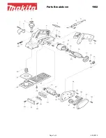
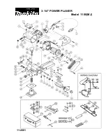
1902
Brand: Makita Pages: 2
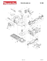
1912B
Brand: Makita Pages: 3
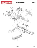
KP0810
Brand: Makita Pages: 3
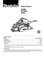
1900B
Brand: Makita Pages: 12
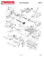
KP312
Brand: Makita Pages: 3
KP0800
Brand: Makita Pages: 8
KP0810
Brand: Makita Pages: 11
1911B
Brand: Makita Pages: 44
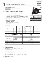
N1923B
Brand: Makita Pages: 60
M1902
Brand: Makita Pages: 19
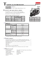
KP0800
Brand: Makita Pages: 56
BKP140
Brand: Makita Pages: 10
HG 1100
Brand: Makita Pages: 4
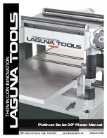
Platinum Series
Brand: Laguna Tools Pages: 42
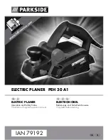
PEH 30 A1 ELECTRIC PLANER
Brand: Parkside Pages: 25
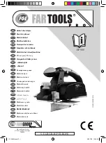
EP 900
Brand: Far Tools Pages: 74
PHA 12 B2
Brand: Parkside Pages: 132
5240
Brand: Oliver Pages: 59


