Model: BCM241T08
Serial No. __________
CONGRATULATIONS
Thank you for purchasing this Hitachi product.
Please read these instructions carefully.
For additional assistance please call Toll Free
800.HITACHI (800.448.2244) or
or visit our website at www.hitachi.us/tv.
Keep this owner’s guide for future reference.
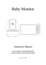
Record the serial number of your
Baby Monitor for future reference. This information
is located on the bottom of the camera unit.
Revision 11042014
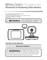
Wireless Video Monitor
with 2.4” Touch Panel Display
*
Owner’s Guide
*(2.36” Diagonal)
E
N
G
L
IS
H
E
S
P
A
O
L