background image

Please be sure to hand it over to the customer using.

The customer using should read it before use.

•  

This instruction manual explains the handling of Hitachi L-type Electric chain hoist in details so please 
ensure to read over it until the end and use it correctly. Facility managers and workers who will use the 
equipment should read this manual.

•  

This instruction manual describes the items specific to the L-type Electric chain hoist. The attached 
"Electric chain hoist owner’s manual" describes the general handling method of Electric chain hoists, so 
read the manuals together and use them correctly.

•  

When the installation / operation / maintenance are inappropriate, the electric chain hoist cannot be used 
smoothly, and may cause unexpected troubles and accidents.

•  

After reading, please carefully store all the manuals together and utilize these during maintenance and 
inspection.

•  

Please note that we do not guarantee Electric chain hoists that are remodeled.

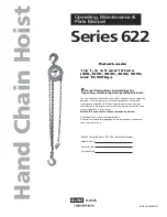
Hitachi Electric Chain Hoist

Service Manual

L - type  (single  speed)
LN - type  (dual  speed)
LS - type  (single  phase)

Original version

Summary of Contents for L Series

Page 1: ...he attached Electric chain hoist owner s manual describes the general handling method of Electric chain hoists so read the manuals together and use them correctly When the installation operation maintenance are inappropriate the electric chain hoist cannot be used smoothly and may cause unexpected troubles and accidents After reading please carefully store all the manuals together and utilize thes...

Page 2: ......

Page 3: ...ts are important always observe them After reading always store this manual where it can be read by those who use it Safety Precautions This is a dangerous situation that if not avoided poses immanent death or serious injury This is a dangerous situation that if not avoided could lead to death or serious injury This is a dangerous situation that if not avoided could lead to minor as semi serious i...

Page 4: ...4 Installation steps 11 4 1 About attaching the Chain Container 11 4 2 About the installation of cables 12 5 Cautions for use 13 6 Maintenance and inspection 14 6 1 Daily inspection 14 6 2 Inspection before starting work 14 6 3 Periodic voluntary inspection 15 6 4 Disassembly Assembly 15 6 5 Inspection of the electromagnetic brake 21 6 6 Adjustment of the electromagnetic brake gap 22 6 7 How to in...

Page 5: ...ed the equipment is used in accordance with the cautionary notes given in the instruction manuals on body labels etc and provided the cause of the fault or breakage lies in our design manufacturing or materials etc we will repair it free of charge Even within the warranty period repair charges may apply for the following situations 1 The fault is caused by the failure to adhere to the usage method...

Page 6: ...C 40ºC no freezing Humidity 90 or less no condensation Classification ISO M4 FEM 1Am Noise level 75dB or less A scale measured at 1m away from the hoist Color Orange Munsell 2 5YR 6 12 In the special circumstances shown below the standard specifications cannot be used so please contact us separately 1 When using in acidic alkaline salty or in corrosive gas environments 2 When the ambient temperatu...

Page 7: ...1 LS type single speed single phase 5 0 6 0 3 6 4 3 2 3 Speed specification Machine type Motor insulation class L type Class E LN type Class F LS type Class E 2 4 Motor specification Capacity 150 500kg 150 500kg Low lift High lift Low lift High lift L type 29 32 33 36 LN type 32 35 36 39 LS type 34 37 35 38 Function Standard Model With Emergency Stop 2 5 Approximate weight Unit m min Unit kg ...

Page 8: ... 6 Product view Push button Lower hook part Decelerator brake side Upper hook part Specification nameplate position Motor side Chain Capacity Nameplate position Chain bucket Operation plug 6P Power plug 9P ...

Page 9: ... 5 2 7 Outer dimensions L type LN type LS type Z 468 A 181 183 181 B 182 210 C 125 D 165 185 165 D 200 E 584 a 27 b 35 c 35 5 d 27 Dimension mm D With Emergency Stop Device ...

Page 10: ...mounting cannot be maintained Places where the temperature goes lower than 10 C or higher than 40 C or where the humidity exceeds 90 Places with a lot of acids or salts It will cause severe wear and tear of the parts and there is a risk of injury from falling loads caused by mechanical failure etc Places with organic solvents or explosive dust There is a danger of ignition explosion etc Places sub...

Page 11: ...of the power cable T and R terminals 1 Power supply We recommend cable feeding for the power supply 2 Mounting location 1 In the case of a suspended type Electric chain hoist please remove the paint and rusts from the above before of mounting 2 In the case of a transverse trolley attached Electric chain hoist since it is grounded by contact of the trolley wheels and the rail do not paint the conta...

Page 12: ... 8 3 3 Connection diagram 1 L type single speed wiring diagram ...

Page 13: ... 9 2 LN type dual speed wiring diagram ...

Page 14: ... 10 3 LS type single phase wiring diagram ...

Page 15: ...er as follows 1 Align the hole positions of the Chain Container and the body frame and insert the two pins attached to the frame 2 Tighten the nuts with spring washers in between DANGER Please ensure that the bolts and nuts are fitted securely without slack or miss There is a risk of serious accidents from the fall of the Chain Container ...

Page 16: ... at the tip of the PB wire into the corner hole at the bottom right of the cover and tighten the screw with the cable stopper to prevent its detachment 4 2 About the installation of cables Please install the power cable and the push button cable as follows 1 Check whether the plug is 9P for power supply or 6P for operation 2 Push the plugs into the switch part as shown in the figure below There wi...

Page 17: ...ated exceeded the ratings the temperature of various parts of the Electric chain hoist will rise above the allowable limit causing burnout of the motor and shortening the lifetime of the mechanical parts Even when using over a short time in a concentrated manner please do not exceed the prescribed start frequency and duty factor for each model Example When using the L type single speed for 15 minu...

Page 18: ...abnormality stop using immediately and use only after taking appropriate remedies referring to the section General causes of malfunction and measures in the Hitachi Electric chain hoist Owner s Manual It is very dangerous to use in a state of abnormality which can lead to an accident so do not operate 6 1 Daily inspection 6 2 Inspection before starting work Confirmation of operation without load 1...

Page 19: ...tric shocks and fall accidents which are extremely dangerous Ensure to take appropriate measures such as adjustment or replacement Never use other than genuine Hitachi parts for replacement There is a risk of injury due to electric shocks or falls for breakage of parts 6 3 Periodic voluntary inspection 6 4 Disassembly Assembly 1 Disassembly of the housing and the rotor 1 Remove the 6P connector an...

Page 20: ...move 4 screws M6 12 and 4 cover washers only the 4 M6 16 screws in case of LN type and remove the cover B Switch stand packing Screw M5 12 Rotor Housing Screw M6 16 6P 9P connectors P 4 6 2 Cover B Cover washer L LS screw M6 16 LN screw M6 16 L LS 5 Remove the one M5 12 screw then remove the switch stand and the packing 6 Detach the 6P connector and the 9P connector from the inside part P of the m...

Page 21: ...e two screws M4 8 and remove the transformer 3 Remove 7 screws M6 16 and remove the gear case cover and gear case packing 4 Remove the thrust spring seat 2nd stage gear 3rd stage pinion axle C ring 25 3rd stage gear Screw M6 16 Brake gear case cover Screw M6 16 3rd stage gear Axle C ring 25 3rd stage pinion 2nd stage gear Thrust spring seat gear case packing Screw M4 8 Transformer 3 3 2 4 ...

Page 22: ...he upper hook and the sprocket 1 Please disassemble following up to step 5 of the above mentioned 3 How to disassemble the gear 2 Remove the cover B packing collar screws 4 3 Remove the gear case 2 Collar 1st stage pinion 1st stage gear 2nd stage pinion screw cover B packing Collar Gear case 2 5 2 3 ...

Page 23: ... 19 4 Remove the center unit assembly 5 Remove 4 screws 2 on each side M6 12 and remove the upper hook and the sprocket Center unit assembly Screw M6 12 Upper hook Screw M6 12 Sprocket 4 6 5 ...

Page 24: ... the lower hook 1 Remove 2 hexagonal socket head bolts M6 25 nuts M6 and spring washers M6 each 2 Remove the chain hangers and hanger pin Hexagonal socket head bolt M6 25 Hanger Hanger Nut M6 Spring washer M6 1 2 1 Hanger pin ...

Page 25: ...e slip amount from the time of releasing the push button to when the hoisted load stops exceeds the limit given in Table 1 please adjust Table 1 Appropriate slip value and limiting slip value mm Figure 1 Structure of the brake Table 2 Electromagnetic brake gap mm Appropriate slip value 5 15mm Limiting slip value 20mm Appropriate gap 0 3 0 5 Limiting gap 1 0 Screw Lock washer U nut Solenoid Brake s...

Page 26: ...e is no play with the lock washer inserted the brake gap will be set to 0 5 mm 5 Return the U nut slightly about 1 6 of a turn and pull out the lock washer The U nut is tightened by 1 0 mm with one revolution 6 Return the lock washer to its original position as shown in Figure 1 and tight with the screws Measure the thickness dimension H of the brake wheel and if it exceeds the value in Table 3 re...

Page 27: ...unch marks and compare it with the value measured before using the product to ensure there is no deformation Measure the dimension A between punch marks as follows 2 Thickness dimension of the hook Measure the thickness dimension H of the hook and compare it with the value measured before using the product to ensure it is 95 or more of the original value The A and H dimensions in the table below a...

Page 28: ... falls below the value in the table below due to wear wear of not less than 10 of nominal diameter When there is a sever chain also verify the wear condition of the sprocket and sprocket guide at the same time A unit mm Chain Diameter Usage limit dimension d L 6 3 5 7 20 L d 3 Measurement of wear and elongation by the limit gauge 1 Using the attached limit gauge measure the wear and elongation usi...

Page 29: ...hen the limit switch kick in is lower than the specification there is a risk of the brake slippage becoming larger or the limiting spring getting deformed which may lead to serious accidents due to excessive force being applied to the main body or on the limit lever during the operation of the limit switch 3 Confirm contact wear 1 Remove the housing and take out the limit switch in state of shutti...

Page 30: ...5 51 2 25 26 500 22 47 2 22 22 1st gear 150 58 40 2 58 13 250 67 75 2 67 48 500 70 83 2 70 60 2nd pinion Shared 21 53 3 20 91 2nd gear Shared 87 90 3 87 36 3rd pinion 150 500 30 80 5 30 02 250 32 89 4 32 30 3rd gear 150 500 83 60 5 82 64 250 79 26 4 78 42 Spline 1st pinion Both ends Shared 20 86 3 20 36 Motor pinion Shared 21 27 3 20 62 Category Part Name Rated load kg Original dimensions mm Numbe...

Page 31: ...the wear condition of the chain seat 2 Check for abrasion and any collapsing of the tooth portion Judgment criteria 1 There is no abnormal wear 2 There is no abnormal wear or collapsed part Worn parts of the sprocket Unit mm Original dimensions Wear limit L 5 9 5 3 L ...

Page 32: ...on dust before putting in new grease Wipe as needed when oil separated from grease accumulates on the cover or other parts Oiling Location Type of Oil Application Amount Volume Oiling Criteria Upper Lower hook assembly Hook thrust bearing EPINOC grease No 1 JXTG Nippon Oil Energy corp or NIPPECO SEP No 1 NIPPECO LTD About 3g Twice a year Suspention pin Enough to cover the surface Once a year Coupl...

Page 33: ...INION 1 L LS MODEL 812943 OL 1ST PINION 1 1 LN MODEL 4 812942 RELAY ASS Y 1 1 5 812077 ME CAPACITOR 1 1 6 871287 RELAY 2 2 7 812939 GEAR CASE COVER 1 1 8 812934 G PACKING OL 1 1 9 812946 OL 2P ASS Y 1 L LS MODEL 812945 OL 2P ASS Y 1 L LS MODEL 812948 OL 2P ASS Y 1 LN MODEL 812936 OL 2P ASS Y 1 LN MODEL 10 813364 GEAR CASE OL 1 1 11 PAN HEAD SCREW M5x8 2 2 12 PAN HEAD SCREW M4x6 2 2 Part list for O...

Page 34: ... 30 Bill of material of L type ...

Page 35: ... 31 Bill of material of LN type ...

Page 36: ... 32 Bill of material of LS type ...

Page 37: ...0 415V 50Hz 3 346V 50Hz 1 220 240V 50 60Hz 1 1 1 812929 3 220 230 440 460V 60Hz 1 1 1 812914 1 100V 50 60Hz 1 1 7 812807 Spring 4 4 4 8 812806 Brake spring 4 4 4 812928 Brake spring 4 4 9 812805 Brake disk 1 1 1 10 813354 Brake wheel 1 1 1 11 Screw AM6 16 4 4 4 12 812804 Brake base assembly 1 1 1 13 812802 Gear case cover 1 1 1 14 812801 Gear case packing 1 1 1 15 812831 Cable stopper 1 1 16 81287...

Page 38: ...1 41 812007 Coupling 1 1 1 42 813908 Screw for case 4 4 4 43 44 811062 Packing 1 1 1 45 811063 Cable stopper 1 1 1 46 Screw M5 12 2 2 2 47 813850 Packing for lead 1 1 1 48 Screw AM6 12 4 4 4 49 Screw AM6 12 4 4 4 A2 812879 Upper hook assembly 1 1 1 50 812880 Upper hook 1 1 1 51 811140 Stopper A 1 1 1 52 812830 Hook spring A 1 1 1 53 811141 Spring pin 5 36AW 1 1 1 54 55 812966 Center frame 2 2 2 56...

Page 39: ...t 1 1 1 79 812830 Latch spring 1 1 1 80 813896 Latch assembly 1 1 1 Includes S N 78 79 81 812460 U nut M5 1 1 1 82 Hunger assembly 1 1 1 84 85 839710 Chain stopper 1 1 1 86 812533 Retainer 1 1 1 87 812409 U nut M4 2 2 2 88 Screw M4 16 2 2 2 89 813897 Chain bucket Lx 90 813898 Bucket pin 2 2 2 91 Nut M8 2 2 2 92 Spring washer M8 2 2 2 93 End washer M8 2 2 2 95 96 97 812903 Clip 1 1 1 98 Screw AM5 8...

Page 40: ... 2 2 114 116 813515 Contactor HMU12 1 1 1 117 812998 Switch stand 1 1 1 813237 1 1 1 118 812873 Collar 2 2 2 119 812871 Rectifier assembly 1 1 1 120 812872 Bushing 2 2 2 121 Screw WM4 16 2 2 2 122 812976 Connector assembly 1 1 1 123 812876 Packing 1 1 1 124 812875 Side cover 1 1 1 124 813235 1 1 125 Screw AM6 12 4 4 4 126 127 128 129 Screw AM5 12 1 1 1 130 854709 15A8P terminal block 1 1 1 812071 ...

Page 41: ... 1 1 1 1 Not shown 153 813027 Chain gage 6 3 1 1 1 154 813366 Capacitor A 1 1 155 813367 Capacitor base A 1 1 156 Screw AM5 8 1 1 157 Screw WM4 10 2 2 158 813368 capacitor B 1 1 159 813369 Capacitor base B 1 1 160 Screw A4 10 2 2 161 Screw A4 10 4 4 162 813903 Capacity nameplate 500kg 1 813904 490kg 1 813905 250kg 1 813906 150kg 1 163 812193 2PB assembly 3m 1 1 1 812194 2PBH assembly 6m 1 1 1 8125...

Page 42: ...MEMO ...

Page 43: ...MEMO ...

Page 44: ...3 Q3975 2C ...

Reviews: