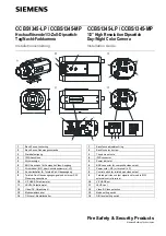
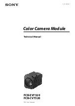
background image

3-CCD Color Camera 

MODEL 

 HV-F31CL


HV-F22CL 
HV-F31CL-S1 
HV-F22CL-S1 

OPERATION MANUAL 


Please read this operation manual carefully for proper operation, and keep it for future reference. 


NOTE:


The model and serial numbers of your product are important for you to keep for your convenience and 

protection.  These numbers appear on the nameplate located on the bottom of the product.  Please record these 
numbers in the spaces provided below, and retain this manual for future reference.


Model No.                                 


Serial No.                                             


Summary of Contents for HV-F22CL

Page 1: ...ion and keep it for future reference NOTE The model and serial numbers of your product are important for you to keep for your convenience and protection These numbers appear on the nameplate located on the bottom of the product Please record these numbers in the spaces provided below and retain this manual for future reference Model No Serial No ...

Page 2: ...ment or near a swimming pool and the like 8 Accessories Do not place this product on an unstable cart stand tripod bracket or table The product may fall causing serious injury to a child or adult and serious damage to the product Use only with a cart stand tripod bracket or table recommended by the manufacturer or sold with the product Any mounting of the product should follow the manufacturer s i...

Page 3: ...are not likely to be walked on or pinched by items placed upon or against them paying particular attention to cords at plug convenience receptacles and the point where they exit from the product 14 Lightning For added protection for this product during a lightning storm or when it is left unattended and unused for long periods of time unplug it from the wall outlet This will prevent damage to the ...

Page 4: ...work by a qualified technician to restore the product to its normal operation e If the product has been dropped or damaged in any way f When the product exhibits a distinct change in performance this indicates a need for service 21 Replacement Parts When replacement parts are required be sure the service technician has used replacement parts specified by the manufacturer or have the same character...

Page 5: ...verwenden z B in der Nähe einer Badewanne eines Waschbeckens einer Küchenspüle eines Waschzubers in einem nassen Keller in der Nähe eines Schwimmbeckens usw 8 Aufstellung Das Erzeugnis nicht auf einen unstabilen Wagen Stand Dreifuß Träger oder Tisch stellen Das Erzeugnis kann sonst herunterfallen und ein kind oder einen Erwachsenen schwer verietzen Außerdem kann das Gerät schwer beschädigt werden ...

Page 6: ...en 12 Erdung oder Polarisierung Dieses Erzeugnis ist mit einem Schutzkontaktstecker mit drei Leitern ausgerüstet mit einem Erdungskontakt Dieser Stecker paßt nur in ein schuko Steckdose Dies ist eine Sicherheitsmaßnahme Wenn Sie den Stecker nicht in die Steckdose stecken können so wenden Sie sich bitte an ihren Elektriker damit er die veraltete Schuts des Schutzkontaktsteckers unwirksam 13 Netzkab...

Page 7: ...hen Sie sich für jegliche Wartung auf qualifiziertes Wartungspersonal 20 Beschädigung die Wartung erfordert Ziehen Sie den Stecker dieses Erzeugnisses aus der Steckdose und wenden Sie sich an qualifiziertes Wartungspersonal wenn eine der folgenden Bedingungen vorliegt a Wenn das Netzkabel oder der Stecker beschädigt ist b Bei Eindringen von Flüssigkeit oder Fremdkörpern in das Gerät c Wenn das Erz...

Page 8: ...e den Wartungstechniker nach der Vollendung von Wartung oder Reparaturarbeiten an diesem Erzeugnis um die Durchführung von Sicherheitsprüfungen um zu bestimmen daß das Erzeugnis im angemissenen Betriebszustand ist 23 Anbringung an der Wand oder an der Decke Das Erzeugnis sollte nur entsprechend den Empfehlungen des Herstellers an einer Wand oder an der Decke angebracht werden 24 Wärme Das Erzeugni...

Page 9: ... Eau et humidité Ne pas utiliser l appareil á proximité d eau ar exemple prés d une baignoire d un lavabo d un évier ou d un bac á lessive dans un sous sol humide ou prés d une piscine etc 8 Accessoires Ne pas placer l appareil sur un chariot un socle un pied un support ou one table instables L appareil pourrait tomber blessant griévement des enfants ou des adultes et étant sérieusement endommagé ...

Page 10: ...se á la terre Ceci est une mesure de sécurité Si la fiche ne rentre pas dans la prise faire remplacer la prise désuéte par un électricien Ne pas rendre vaine la measure de sécurité assurée par cette prise avec mise á la terre 13 Protection du cordon d alimentation Acheminer les cordons d alimentation de facon qu on ne risque pas de marcher dessus ou de les coincer sous un objet placé dessus ou con...

Page 11: ...ommagés b Si du liquide s est renversé sur l appareil ou que des objets sont tombés dedans c Si l appareil a été exposé á la pluie ou á l eau d Si l appareil ne fonctionne pas normalement lorsqu on observe les instructions d utilisation Ne régler que les commandes couvertes par le mode d emploi en effet un réglage incorrect des autres commandes pourrait entrainer des dommages et nécessiteront souv...

Page 12: ...pour s assurer que l appareil est en bon état de marche 23 Montage au mur ou au plafond L appareil ne pourra être monté au mur ou au plafond que de la maniére recommandée par le fabricant 24 Chaleur Eloigner l appareil des sources de chaleur telles que radiateurs appareils de chauffage cuisiniéres et de tour produit engendrant de la chaleur y compris les amplificateurs ...

Page 13: ...in a residential area is likely to cause harmful interference in which case the user will be required to correct the interference at his own expense WARNING Changes or modifications not expressly approved by Hitachi Denshi responsible for compliance could void the user s authority to operate the equipment This product does not exceed the class A class B limits for radio noise emissions from digita...

Page 14: ...ions 7 z Connectors 8 z LENS 10 z Camera mounting 11 z Functions and operations 12 Main function 12 Masking function 20 Black balance White gate function 21 Auto exposure function 22 Sharpness function 25 Focus detection function 28 Other function 29 Appendix 31 z Specifications 33 z Input Output Signals 35 z Camera Link output timing chart 38 z Trigger operation and timing chart HV F31CL HV F31CL...

Page 15: ...l processing LSI a C mount prism three 1 3 inch 800 000 pixels HV F31CL HV F31CL S1 1 2 inch 1 450 000 pixels HV F22CL HV F22CL S1 square CCDs and a Camera Link interface A newly developed multi functional LSI use the accurate 14 bit digital processing technology which performs the high picture quality signal processing and the picture compensating functions beyond the capability of the other conv...

Page 16: ...ic range High quality picture Excellent color reappearance and high definition are materialized by CCD with a high sensitivity micro lens and LSI signal processing technology 6 vector masking Independent six colors masking is the Hitachi innovation for optimizing color balance The saturation and the hue of 6 colors Red blue green cyan magenta and yellow are adjusted independently to deliver the be...

Page 17: ... Power supply Check that the supplied voltage is between 10 5 and 15 VDC Inadequate voltage can affect color fidelity and cause noise while voltage over 15 V can damage the camera z Connectors Confirm the power is off before connecting or disconnecting a signal cable Grasp connectors by the body not the attached wires z Lens The correct lens is important for deriving optimum performance from the c...

Page 18: ...h a soft dry cloth If soiling is severe moisten the cloth with a solution of neutral detergent Afterwards wipe the cover with a dry cloth z Do not use petroleum distillates alcohol or spray type cleaners Transportation Remove the lens install lens mount cap and other attachments Pack the camera carefully in its original or equivalent container Use ample cushioning to protect the camera from physic...

Page 19: ... a pattern in the scene e g a performer wearing a finely striped necktie to result in a Moire pattern The effect should be considered when selecting costumes props and other scene elements 4 Ghosting Strong direct or reflected light near an object of interest can cause ghosting of the object to appear in the picture The effect is more obtrusive with certain iris settings and lens types Select the ...

Page 20: ...System example Lens HV F31CL HV F22CL HV F31CL S1 HV F22CL S1 AC adaptor NOTE The frame grabber should conform to medium configuration HV F31CL HV F22CL or base configuration HV F31CL S1 HV F22CL S1 of Camera Link standard With HV F31CL HV F22CL both the frame grabber and the PC should have a PCI interface of 64bit 66MHz or higher ...

Page 21: ...ls Camera Link connector see Note Digital video output and serial communication Connect to the frame grabber with Camera Link cable Camera mounting screw holes Camera mounting screw holes Lens mount C mount HV F31CL S1 HV F22CL S1 NOTE HV F31CL and HV F22CL have two Camera Link connectors D OUT 1 REMOTE and D OUT 2 HV F31CL S1 and HV F22CL S1 has single Camera Link connector D OUT 1 REMOTE HV F31C...

Page 22: ...1 16 Y1 4 X2 17 X2 4 Y2 17 Y2 5 Xclk 18 Xclk 5 Yclk 18 Yclk 6 X3 19 X3 6 Y3 19 Y3 7 SerTC 20 SerTC 7 NC 20 NC 8 SerTFG 21 SerTFG 8 NC 21 NC 9 NC CC1 22 NC CC1 9 NC 22 NC 10 TRIG CC2 23 TRIG CC2 10 NC 23 NC 11 NC CC3 24 NC CC3 11 NC 24 NC 12 NC CC4 25 NC CC4 12 NC 25 NC 13 GND 26 GND 13 GND 26 GND 1 13 14 26 X0 X2 Y0 Y2 Video and sync output Xclk Yclk Pixel clock output SerTC RXD serial data to cam...

Page 23: ...ight No 6 HD IN TXD to PC No 7 VD IN RXD to camera When the direction is right the serial communication via Camera Link is not available 2 DC IN SYNC connector Hirose HR10A 10R 12PB 01 Pin NO Signal designation 1 GND 2 12V input 3 GND 4 FLASH OUT 5 GND 6 HD IN TXD see Note 7 VD IN RXD see Note 8 GND 9 TRIG H 10 TRIG C 11 12V input 12 GND Matching Plug Hirose HR10A 10P 12S These switches should be ...

Page 24: ...case of a three elements CCD system C mount camera the lens incidence and exit distances are important If separation is too short color irregularity is apt to occur at the top and bottom of the image Conversely if too long where the lens iris is a nearly fully open resolution is impaired while shading and flare can seriously detract from image quality When using 3 CCD color system camera it is als...

Page 25: ... at the top and bottom These allow mounting to either a tripod or a mounting bracket Screw type U 1 4 20 Length 4 5 to 6 mm L Screws longer than 6 mm can cause internal damage while less than 5 mm prevents secure fastening and risks dropping to cause damage and injury ...

Page 26: ...lack level adjustment Manual adjustment Setting value 302Bxxzz h xx 80h to 7Fh default 00h zz undefined Set the value toward 80h side to lower black level toward 7Fh side to raise that 2 SHARPNESS Sharpness level adjustment object contour correction OFF Contour correction is disabled Setting value 200210EF h Manual adjustment Setting value 302Cxxzz h xx 80h to 7Fh default 00h zz undefined Set xx t...

Page 27: ... ch gain Setting value 3002xxzz h xx 80h to 7Fh signed default 00h zz undefined Gain is reduced at 80h side and raised at 7Fh side 4 GAIN Electrical sensitivity adjustment Gain mode MANUAL Gain is manually adjustable from 0 to 12 dB AUTO Gain is automatically adjusted from 0 to 12 dB for proper video level Setting value 2004xxCF h xx 10h MANUAL 20h AUTO Manual adjustment Manual adjustment is avail...

Page 28: ...xxF8 h xx 03h MANUAL 05h AUTO 00h OFF Manual adjustment Shutter speed adjustment is available on MANUAL mode Setting value 3038xxxx h xxxx FFC5h to 036Ch signed HV F22 FF89h to 0327h signed HV F31 Electronic shutter speed can be set in the range of 4 to 1 100 000 second Shutter speed is calculated as follows Note OFF_VALUE equals to 15 in HV F22 or 30 in HV F31 1 In the case that shutter speed is ...

Page 29: ...0001h OFF_VALUE Shutter Speed Exp Exposure time 1 7 5 sec for HV F31CL 10001h 30 1 7 5 FFFDh Calculate exposure time from value Shutter Speed sec 10001h nnnnh OFF_VALUE 6 AUTO EXPOSURE Both gain and shutter speed are always adjusted automatically for proper video level Adjust the video level manually Manual adjustment Setting value 3039xxzz h xx 80h to 7Fh signed default 00h zz undefined The video...

Page 30: ...20xFD h x 0 ON 2 OFF Manual adjustment TOTAL Adjust total R G and B gamma curve Setting value 3027xxzz h R OFFSET Adjust only R gamma curve Setting value 3003xxzz h B OFFSET Adjust only B gamma curve Setting value 3005xxzz h xx 80h to 7Fh signed default 00h zz undefined Dark component gradation is reduced toward 80h and increased toward 7Fh 9 TRIGGER Set external trigger operation available ON OFF...

Page 31: ... output NARROW Setting value 204801F0 h MIDDLE Setting value 204802F0 h WIDE Setting value 204803F0 h VARIABLE Setting value 20480FF0 h Flash pulse delay Flash pulse width Set the delay time of flash pulse output when Flash pulse width is NARROW MIDDLE WIDE Set the flash pulse width when Flash pulse width is VARIABLE Setting value 30CExxxx h xxxx 8000h to 7FFFh signed The delay time can be varied ...

Page 32: ...alue 200220DF h Shading mode LUMINANCE Auto shading compensation operates to maintain uniform vertical level for the RGB video signals Use with microscopes and other uniformly illuminated equipment Setting value 280100F3 h COLOR Auto shading correction operates to minimize vertical color irregularity in the image Use for non uniformly lit general purpose image material Setting value 280104F3 h FLA...

Page 33: ...ottom 3 Execute white balance adjustment 4 Execute the shading adjustment The video image is flashing during shading adjustment 11 INITIALIZE Return the setting parameters of camera to values at time of release from factory Initialization Setting value 9000FF h 12 FILE SAVE Save the setting data to an EEPROM 4 sets of memory are available Setting value 61010x h x 1 ch1 2 ch2 3 ch3 4 ch4 13 FILE LO...

Page 34: ...lue 3049xxzz h Cy saturation Setting value 304Axxzz h Mg saturation Setting value 304Bxxzz h xx 80h to 7Fh signed default 00h zz undefined Saturation decreases toward 80h 100 and increase toward 7Fh 100 Manual adjustment Hue R hue Setting value 3040xxzz h G hue Setting value 3041xxzz h B hue Setting value 3042xxzz h Ye hue Setting value 3043xxzz h Cy hue Setting value 3044xxzz h Mg hue Setting val...

Page 35: ...ST One Push ABB Adjusts standard level for R B BLACK and independent of R B BLACK Setting value 4020 h Be sure that a lens iris is completely closed in advance 2 WHITE GATE Square window for detecting white balance appears in the screen White balance is computed only in the window INDICATE The white gate window is selectable visible ON or invisible OFF Setting value 20170xF3 h x 0 OFF 4 ON ON OFF ...

Page 36: ...CF h x 0 50 50 1 25 75 2 15 85 3 0 100 Set auto level control for Peak or Average in 4 steps of 50 50 15 85 25 75 or 0 100 At high Average setting background may be difficult to see in picture bright components Increasing the Peak setting may render spotlighted components easier to see 2 ALC SPEED AGC and AES response speed Manual adjustment Setting value 28110xFC h x 0 SLOW 1 STANDARD 2 FAST SLOW...

Page 37: ... GATE for detecting the AUTO EXPOSURE video signal is set in lines 1 2 to 7 8 The area is not shown on the screen Manual setting Detect area of ALC GATE can be arranged in 8 x 8 matrix areas Setting value 282xyy00 h x line selection 0 line1 to 7 line8 yy column selection Set 1 in detect area and 0 in non detect area to generate 8 binary digits left side MSB right side LSB Convert the 8 binary digi...

Page 38: ...0 0 1 1 1 1 0 0 4 0 1 1 1 1 1 0 0 5 0 1 1 1 1 1 0 0 6 0 1 1 1 1 1 0 0 7 0 1 1 1 1 1 0 0 Line x 8 0 1 1 1 1 1 0 0 ALC GATE line1 setting 28 20 00 00 h ALC GATE line2 setting 28 21 00 00 h ALC GATE line3 setting 28 22 3C 00 h ALC GATE line4 setting 28 23 7C 00 h ALC GATE line5 setting 28 24 7C 00 h ALC GATE line6 setting 28 25 7C 00 h ALC GATE line7 setting 28 26 7C 00 h ALC GATE line8 setting 28 27...

Page 39: ...g value Use mainly to avoid noise enhancement in dark signal components Manual adjustment Setting value 3053xxzz h xx 80h to 7Fh signed zz undefined Setting toward 7Fh to reduce the sharpness level and expand the video signal level range 3 SHARPNESS CLISP Excessive sharpness signal upper the setting value is removed But set the value too low some detailed image can be dim Manual adjustment Setting...

Page 40: ...1 width level can be set in any combination Select channel 1 or 2 then set the hue for fine adjusting ON OFF Setting value 2035x0EF h x 0 OFF 1 ON Manual setting Select one from 6 primary color areas and then adjust finely in the area Color select Setting value 20200xF8 h x 0 R Mg 1 Mg B 2 B Cy 3 Cy G 4 G Ye 5 Ye R Fine adjust Setting value 3059xxzz h xx 80h to 7Ch signed zz undefined Hue moves cl...

Page 41: ... for a stark image 7 SHARPNESS COLOR DTL Ch2 Same function as COLOR DTL Ch1 Ch 1 and 2 can be used as independent functions ON OFF Setting value 2035x0DF h x 0 OFF 2 ON Manual setting Color select Setting value 20210xF8 h x 0 R Mg 1 Mg B 2 B Cy 3 Cy G 4 G Ye 5 Ye R Fine adjust Setting value 306Bxxzz h xx 80h to 7Ch signed zz undefined Hue moves clockwise One Push AUTO SETUP Setting value 41D1 h 8 ...

Page 42: ...cus gate window is selectable visible ON invisible OFF Setting value 20170xF3 h x 0 OFF C ON GATE POSITION H POSITION Setting value 30B1xxzz h xx AFh to 51h signed HV F22 C4h to 3Ch signed HV F31 zz undefined V POSITION Setting value 30B2xxzz h xx C4h to 3Ch signed HV F22 D4h to 2Ch signed HV F31 zz undefined GATE SIZE WIDTH Setting value 30B3xxzz h xx 00h to 14h HV F22 00h to 0Fh HV F31 zz undefi...

Page 43: ...xFC h x 1 MODE1 2 MODE2 Although MODE 2 provides greater noise reduction there is some sacrifice in resolution 2 COLOR BAR Color Bars test pattern is available Setting value 20080xFE h x 1 ON 0 OFF 3 NEGA Brightness and darkness of picture is reversed Setting value 2008x0EF h x 1 ON 0 OFF 4 EXT IN 75 ohm Termination resistance of External HD VD input is selectable OFF High Z Setting value 2011807F...

Page 44: ...lue 3034xxzz h xx 80h to 7Fh zz undefined See page 45 External sync timing about variable range 6 PIXEL CONCEALMENT White spot defect on picture element can be compensated Setting value 20330xFE h x 1 ON 0 OFF For image processing use the setting OFF might be better since the compensated data is not precise ...

Page 45: ...on or decrease the gain to provide a proper video level 15h The color temperature is too high making it impossible to reach the optimum value in adjustment If there is no problem in practical application use the camera under the current condition Add a filter to the lens or illumination to decrease the color temperature 16h The color temperature is too low making it impossible to reach the optimum...

Page 46: ...32 Error code Countermeasure 1Fh The color saturation is too low making it impossible to reach the optimum value 24h Release the long shutter mode 25h Release the external trigger mode ...

Page 47: ...4 65 V µm 4 65 H 4 65 V µm Effective image area 4 77 H 3 58 V mm 6 33 H 4 77 V mm Scanning system Progressive scan Sync system Internal or External HD VD automatic switching Standard sensitivity F5 6 at 2000 lx 1 30 sec shutter F8 at 2000 lx 1 30 sec shutter Geometric distortion Full screen 0 not including lens characteristics Registration Full screen 0 05 not including lens characteristics Vertic...

Page 48: ... RGB 3x10 bit Base RGB 3x8 bit Medium RGB 3x10 bit Base RGB 3x8 bit Pixel clock frequency 28 8 MHz Maximum frame rate Approx 30 fps Approx 15 fps Power supply voltage 12 V rated Stable operation at 10 5 to 15 Vdc and neither ripple nor noise Power consumption Approx 6 W Approx 6 5 W Dimensions 65 W x 65 H x 130 D mm Mass Approx 600 g without lens Ambient temperature Operating 0 to 40 Storage 20 to...

Page 49: ...1CL HV F22CL RGB 3 x 10 bit HV F31CL S1 HV F22CL S1 RGB 3 x 8 bit 3 Sync signal output Pixel clock 28 8 MHz Horizontal sync LVAL HV F31CL HV F31CL S1 23 72 kHz HV F22CL HV F22CL S1 16 09 kHz Vertical sync FVAL HV F31CL HV F31CL S1 29 95 Hz HV F22CL HV F22CL S1 15 06 Hz 4 Serial communication 1 Communication system Full duplex 2 Baud rate 19200 bps 3 Sync system Start stop system ...

Page 50: ...ld be less than 0 5 second 8 Error correction Request repeat system 5 External trigger input see NOTE 2 External trigger input is assigned on CC2 port 6 Signal level LVDS 290mVp p with 100Ω termination 2 DC IN SYNC input and output DC IN SYNC connector 1 External HD VD signal input see NOTE 1 HD VD 2 to 5 Vp p Negative 2 External trigger signal input Photo coupler see NOTE 2 low 0 Vdc high 3 to 24...

Page 51: ... Stable operation at 10 5 to 15 VDC neither ripple nor noise 3 External trigger input TRIG IN connector see NOTE 2 low 0 Vdc high 2 to 5 Vdc NOTE 1 Both external HD VD input and serial communication are not available at the same time See page 9 NOTE 2 Only one input is available for external trigger among Camera Link DC IN SYNC and TRIG IN Set unused trigger inputs to be open or Low GND level ...

Page 52: ...timing chart HV F31CL HV F31CL S1 Horizontal timing 1 clk 34 7 ns Vertical timing 1 H 1214 clk 42 1 us HD LVAL VIDEO 96 clk Active Picture 94 clk 1024 clk 1214 clk 0 clk Active Picture 768 H 792 H 3 H 9 H 12 H VD FVAL VIDEO ...

Page 53: ...2CL HV F22CL S1 Horizontal timing 1 clk 34 7 ns Vertical timing 1 H 1790 clk 62 2 us HD LVAL VIDEO 96 clk Active Picture 300 clk 1360 clk 1790 clk 34 clk Active Picture 1024 H 1068 H 3 H 17 H 24 H VD FVAL VIDEO ...

Page 54: ...C N C N C N C N C N C Y0 Y1 Y2 Y3 Previous Cycle Next Cycle Yclk R7 R6 B3 B2 N C R9 R1 R0 N C N C N C N C G2 G1 N C N C DVAL FVAL LVAL N C VD HD DVAL FVAL LVAL 34 7 ns 4 96 ns 34 7 ns 4 96 ns N C B9 B8 G9 G8 R9 R8 B7 B6 B5 B4 B3 B2 G7 G6 G5 G4 G3 G2 R7 R6 R5 R4 R3 R2 X0 X1 X2 X3 Previous Cycle Next Cycle Xclk R9 R8 B5 B4 G4 G3 R3 R2 N C VD HD DVAL FVAL LVAL 34 7 ns 4 96 ns HV F31CL HV F22CL HV F31...

Page 55: ...d Note Exposure setting has following 2 types a Preset exposure mode Exposure delay A 2 us to 263 96 ms Variable Flash pulse width B 6 us 46 us 246 us Selectable b Variable exposure mode Exposure delay A 2 us Constant Flash pulse width B 4 us to 263 96 ms Variable External Trigger Internal VD 6 to 7H cam 253 to 295us Exposure 1H cam 42us Frame reset Flash Pulse Output Internal HD External Trigger ...

Page 56: ...posure 30us Frame reset Trigger pulse width 43us 4 0us 12H cam 506us blank 18 to 19H 801us 1 Frame 33 3ms 30FPS 2 Pulse width control exposure mode Mode 1 When external trigger signal is high active light pulse begins at the rising edge of the trigger signal and ends at the falling edge At the trigger signal falling edge the internal VD signal is reset and the video data are transmitted The flash ...

Page 57: ...ms Variable Flash pulse width B 6 us 46 us 246 us Selectable b Variable exposure mode Exposure delay A 2 us Constant Flash pulse width B 4 us to 263 96 ms Variable External Trigger Internal VD 6 to 7H cam 373 to 435us Exposure 1H cam 62us Frame reset Flash Pulse Output Internal HD External Trigger A Internal VD 1Frame 66 7ms 15FPS Internal Video A B C D A VD 3H 186us DATA transfer Exposure Flash P...

Page 58: ...itted The flash pulse output that synchronizes to external trigger is not used in this mode 1 Frame 66 7ms 15FPS External Trigger High active A Internal VD minimum period 1V Internal Video A B C D A VD 3H 186us DATA transfer Exposure Internal VD Internal Video DATA transfer Internal HD 1H cam 62us 3H cam 186us A DATA transfer START 1 75ms External Trigger 6 to 7H cam 373 to 435us Exposure 21us Fra...

Page 59: ...e external synchronization HD F31 38 89us 1120clock F22 58 82us 1694clock F31 42 15us F22 62 15us VD F31 789H F22 1065H Frame rate setting under 15FPS or 541H Frame rate setting 30FPS F31 792H F22 1068H Frame rate setting under 15FPS or 544H Frame rate setting 30FPS Clock 28 8 MHz 0 005 3H F31 3 26us 94clock F22 3 33us 96clock ...

Page 60: ...46 Dimensions 32 5 1 65 2 20 1 32 5 1 65 2 2 1 4 UNC DEPTH 7 37 0 14 0 5 90 0 20 1 14 0 5 90 0 52 0 130 2 2 1 4 UNC DEPTH 7 HV F31CL HV F22CL HV F31CL S1 HV F22CL S1 2 x 2 M3 Unit mm ...

Reviews: