Hitachi HT-L55, Service Manual
The Hitachi HT-L55 Service Manual is a comprehensive user's guide that provides detailed instructions for operating and maintaining this exceptional product. You can easily download this manual for free from manualshive.com, ensuring a hassle-free experience with your Hitachi HT-L55 and making the most of its features.
Share
Download


Reviews:
No comments
Related manuals for HT-L55
301
Brand: Garrard Pages: 33
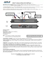
P
Brand: iHold Music Pages: 2

T35
Brand: Harman Kardon Pages: 9
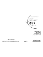
T3
Brand: JB Systems Pages: 26

210
Brand: Garrard Pages: 8
Encore
Brand: QuVIS Pages: 152
RM Series
Brand: Galaxy Audio Pages: 12
T20
Brand: Harman Kardon Pages: 8

W602
Brand: Magnavox Pages: 18

Piccolo
Brand: I.A.V. Pages: 13
HTT 101
Brand: Caliber Pages: 16
ALVA TT
Brand: Cambridge Audio Pages: 13

Moto
Brand: MAJORITY Pages: 104
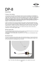
DP-8
Brand: H. H. MORCH Pages: 10
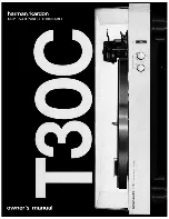
T30C
Brand: Harman Kardon Pages: 9

ST-8
Brand: Harmon/Kardon Pages: 9

DX300
Brand: iBasso Audio Pages: 64
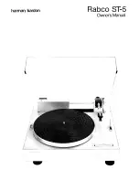
Rabco ST5
Brand: Harman Kardon Pages: 8


