background image


HT-4139-28/48 Scanner


Maintenance Manual 


Summary of Contents for HT-4139-28

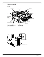
Page 1: ...HT 4139 28 48 Scanner Maintenance Manual ...

Page 2: ......

Page 3: ... Back and Cover Glass Back H3 5 3 3 3 Cleaning the Pick Roller the Separator Roller the Reverse Roller H3 6 3 3 4Cleaning the Drive Roller H3 7 3 3 5Cleaning the Pinch Roller H3 7 3 3 6Cleaning the Imprinting Head Pin H3 7 3 3 7Cleaning Platen H3 8 3 3 8Cleaning the Photo Sensor H3 8 3 3 9Cleaning the Ultra Sonic Sensor H3 9 3 3 10Cleaning the Hopper Guide H3 9 3 3 11 Cleaning the Scanner ASSY H3 ...

Page 4: ... K H8 11 8 3 3 Replacing the DRV P K CPS614 P K H8 12 8 3 4 Replacing the SS P K ASSY CPS618 P K H8 13 8 3 5 Replacing the Scanner ASSY Front H8 14 8 3 6 Replacing the SS Sensor Ultra Sonic Sensor H8 16 8 3 7 Replacing the Hopper ASSY H8 17 8 3 8 Replacing the Stacker H8 18 8 3 9 Replacing the Imprinting Head Assembly H8 19 8 3 10 Replacing the Scanner ASSY Back H8 20 8 3 11 Replacing the Lamp Inv...

Page 5: ... 50 8 3 39 Replacing the Gear SP H8 51 8 3 40 Replacing the F L Sensor H8 52 8 3 41 Mechanism M ASSY Cable Routing H8 53 9 Adjusting H9 1 9 1 Checking the Tension of the Belt H9 1 9 2 Checking the Upper Guide Gap H9 3 9 3 Checking the Interlock Switch INL ASSY H9 4 9 4 Checking the pressure of the Reverse Roller H9 5 9 5 Adjusting the Imprinting Gap H9 6 9 6 Checking the pressure of the Reverse Ro...

Page 6: ... be tested while for other procedures the device must be connected to the host 1 1 Maintenance Contents Contents 1 Preface 2 P arts and F unctions 3 P eriodical M aintenance Routine M aintenance Procedures 4 Diagnostic Tools 5 Off Line Operation 6 Auto calibration 7 Maintenance Tools 8 Replacing Parts Proced ures on Replacing P arts 9 Adjusting B elt Tension Gap etc H1 1 ...

Page 7: ... 2 1 Parts Main power switch Hopper Sheet Guide Power switch Stacker R Top Latch Button Power Connector Top Cover Cover for accessing ink ribbon Stacker A Main Cover L Main Latch Button Control Panel Setting switch USB Connecter ...

Page 8: ...turned ON LEDCheck Mode 2 The Status LED will turn OFF during initialization of the program 3 4 During Inline Loop Mode the Status LED will start blinking The Power and Status LED will both turn OFF and steps 2 4 will repeat itself Local Test Mode Press Switch 8 to turn ON Power Power LED Green Status LED Orange Action 1 The Power LED and the Status LED will be lit for 0 5 seconds after the Power ...

Page 9: ...ed to control the level of sheets 2 Hopper Mechanism Hopper has a swing mechanism by the hopper motor Its stroke is 55mm Detection of vertical position is controlled by the sensor F L L L 3 Stacker Mechanism Stacker Mechanism is a free fall type Two stackers are equipped in the device and sheets are ejected to two trays separately by switching gate Ejecting speed is controlled by the stepping moto...

Page 10: ...itch USB2 0 Hi Speed PickMotor Main Motor Eject Motor Break Motor T1 Motor Hopper Motor Mirror Motor F Stepping Printer 24dot dot impact Ribbon Motor DC Motor Gate Solenoid LEDs PC11 20 21 41 42 43 51 PhotoDiodes LEDs PC22 PhotoDiodes UltraSonic Transmitter Panel LEDs Panel SW Switches CoverOpen Feed Level Low Limit ID SW Rotary SW Temp Sensor Power State Suspend Start Stop Pause SH A D ADC MPU Bu...

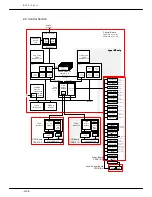
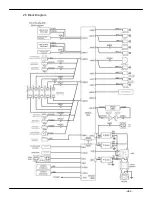
Page 11: ... H2 5 2 5 Block Diagram ...

Page 12: ...Control Section consists of some blocks as shown in the Block Diagram 1 CCD Sensor Signal processing 2 Image processing Image Processor 3 Video Memory 4 Transport Control 5 USB Control 6 Microcomputer Control ...

Page 13: ...r Clean the Ultra Sonic Sensor 3 3 9 Hopper Guide Check the movement of the Hopper Guide 3 3 1 0 Scanner ASSY Front 3 3 1 1 Scanner ASSY Back 1 Clean the Mirror No 1 3 and the Lens on the Scanner ASSY Gears Applying grease on the Gear SP Separator Gear and Gear Reverse 3 8 3 3 9 Guide Latch Check and adjust the Guide Latch Also apply grease on the left and right Latches 8 3 1 9 Guide Gap Left and ...

Page 14: ...r 2 8 2 1 9 Gear S P Pick Unit Gears 8 3 39 10 Washer 1 Axle bearing of the Separator Roller 2 8 2 1 11 Washer 2 Axle bearing of the Separator Roller 2 8 2 1 12 Gear Reverse 3 Axle bearing on the Reverse Roller 8 2 2 13 Pick Gear Gear on the Pick Roller Including for Model HT F4139 94 8 2 1 14 Pick Drive Gear 2 Gear on the Pick Drive 8 2 2 15 Reverse ASSY Including the Torque Limiter 8 3 16 16 Cov...

Page 15: ...0 2000K Characters 3 18 Dummy Y 4181 4 1 5 About 1000K sheets Sales Company Replaced by customer 1 Rollers for paper feeding deteriorate its material and lose friction coefficient Due to this the performance is getting lower The number of sheets for part replacement is based on the test paper 040 7 4 A4 landscape The number might depend on paper size and quality 2 Fluorescent lamp loses light inte...

Page 16: ...he device Lower Mirror Surface Cover Sheet Surface Side view of the Cover Sheet from the left side Remove debris and paper scraps in the area Removing the Cover Sheet Slide the Cover Sheet to the right and pull the Cover Sheet down To attach the Cover Sheet slide it back to the left If the Cover Sheet is attached incorrectly the fluorescent light could get damaged Cover Sheet Cover Sheet Lower Mir...

Page 17: ...the Lower Mirror and the Cover Sheet it may affect the reader 3 3 2 Cleaning the Lower Mirror Back and Cover Glass Back Use gauze soaked in ethanol to wipe the debris and paper scraps from the Lower Mirror Back and Cover Glass Back Cover Glass Back 48 Duplex Model Lower Mirror Back 48 Duplex Model If the fabric from the gauze is left on the Lower Mirror Back and Cover Glass Back it may affect the ...

Page 18: ...oaked in ethanol to wipe debris and paper scraps from Pick Roller and the Separator Roller Inspect the Roller for dirt wear or damage Pick Roller Separator Roller リ Cleaning the Reverse Roller Use gauze soaked in ethanol to wipe the debris and paper scraps from the surface of the Reverse Roller Inspect the Roller for dirt wear or damage Reverse Roller ...

Page 19: ...spect the Drive Roller for dirt wear or damage Note Do not damage Roller 3 3 5 Cleaning the Pinch Roller Pinch Roller T1 is made up of plastic bearing Use gauze soaked in ethanol to wipe the debris and paper scraps from the Pinch Roller Pinch Rollers T2 T7 are made up of metallic bearing Use gauze soaked in ethanol to wipe debris and paper scraps from the Pinch Roller Inspect the Drive Roller for ...

Page 20: ...ten Use gauze soaked in ethanol to wipe the ink Platen 3 3 8 Cleaning the Photo Sensor After cleaning the Photo Sensor run the Auto Calibration Test Use gauze soaked in ethanol to wipe the tip of the Photo Sensor Glass Part Emittor Emittor ...

Page 21: ...cause errors Transmitter Receptor 3 3 10 Cleaning the Hopper Guide Grab the Part A of the Hopper Guide as shown below and slide it to the direction of the arrows Check if it slides smoothly A 3 3 11 Cleaning the Scanner ASSY 8 3 5 Remove the Scanner ASSY from the device For instructions please refer to 8 3 10 Replacing the Scanner ASSY Back Clean the debris on Mirror No 1 3 and the Lens using the ...

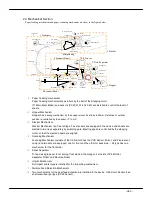
Page 22: ...REV0 10 02 15 H3 10 Lens Mirror Motor Mirror No 1 Mirror No 3 Mirror No 2 ...

Page 23: ... describes diagnostic items for each operation Section 4 2 describes diagnostic order when parts are replaced Diagnostics Off Line Test Auto Calibration Off Line Test Inline Loop Test Maintenance Tool 1 Information on Device Operation 2 Firmware Download 3 Load Save Device Unique Information 4 Memory Dump Low Electric Power Mode Parameter Setting Scanner Utility See he Instruction Manual ...

Page 24: ...r Replace ASAP Parts Photo systems Maintenance M 6 6 1 G H J Replacement Fluorescent lamp Maintenance M 8 2 3 J Inverter Lighting tool Maintenance M 8 3 11 K Front Scanner ASSY Maintenance M 8 3 5 L Fluorescent lamp Maintenance M 8 2 4 J Inverter Lighting tool Maintenance M 8 3 12 K Back Scanner ASSY ASSY Maintenance M 8 3 10 L P K Maintenance M 8 3 MAIN CPS619 P K Maintenance M 8 3 2 M N DRV CPS6...

Page 25: ...t 5 4 2 Host PC 6 2 1 Auto Calibration 3 3 3 3 3 2 2 2 2 2 2 3 2 2 2 4 6 1 3 Maintenance Tool 7 3 1 Information on Device Operation 1 1 1 1 7 1 3 2 Firmware Download 3 1 2 1 7 2 3 3 Load Save Device Unique Information 1 4 7 3 3 4 Memory Dump 7 4 4 Checking Cleaning t Replacing 4 1 Checking 1 1 1 1 1 1 2 3 4 2 Cleaning 2 2 2 2 2 2 3 3 3 4 3 t 3 2 4 9 4 4 Replacing 4 4 4 4 4 1 1 1 1 1 1 2 1 1 2 2 2 ...

Page 26: ... CPS619 2 When problem can not be fixed by the procedure 1 1 Replace the MAIN P K ASSY CPS619 Refer to 8 3 2 MAIN P K ASSY CPS619 2 Power on the device If device control program is attached to the maintenance part download the firmware Refer to 7 2 Down load 3 Power cycle the device Off and On 4 Set the operation information by the scanner utility See 2 6 1 Operation Parameter Setting of the Instr...

Page 27: ...an the test sheets and compare scanned data with the data stored in the device TEST SHEET 040 7 4 5 4 2 Inline Loop Test Repeat IPL Initial Program Load operation mainly used in manufacturing QA process 5 5 No Operation Item Operation Ref LED Power LED Status LED 1 Off line Test Set the switch 8 and power on the device 2 Inline Loop Test Set the switch 9 and power on the device Rotary Switch USB C...

Page 28: ...en all sheets are scanned the LED brinks slowly 3 Error does not make any change To recover error open covers for feed and ejection part and remove jammed sheets and put sheets on the Input tray 4 When the test is completed power off the device 5 4 Inline Loop Test Power LED Status LED Operation 1 Set the switch 9 and power on the device During the Inline Loop test the Status LED blinks fast If er...

Page 29: ... in the device package 6 1 Procedure for Auto Calibration Run the software Scanner Maintenance 1 Press START button 2 Press All Programs 3 Select HT 4139 Image Scanner 4 Select Scanner Maintenance 1 Date of measurement Date is transferred from the PC and displayed on the screen automatically 2 Number of sheets for measurement Put 5 for this 3 DO NOT PUT ANY SHEETS ON THE TRAY FOR THE PHOTO AMPLIFI...

Page 30: ...C22N UltraSonic Sensor and Hardware Test will Start CAUTION IF THERE ARE NOT ENOUGH PAPERS ON THE TRAY THE LEFT SCREEN WILL KEEP POPPING UP CAUTION MAKE SURE THE DIRECTION OF THE PAPER IS THE SAME AS THE PICTURE BELOW 8 PC22N Test is Running 9 UltraSonic Sensor Test is Running 10 Hardware Test is Running ...

Page 31: ...oll down the slide bar and check the results of the Auto Calibration for the Photo Amplifier the PC22N the UltraSonic Sensor the Hardware and the Sheet Feeding Speed and confirm that all Results are OK 16 If the Results are OK the test is finished Press Confirmed Caution In case of failure that could not be adjusted by the Auto Calibration investigate the causes and fix the issue to pass the Auto ...

Page 32: ...fications cleaning or replacing PC22N may be required Test 3 Auto Calibration of Ultrasonic Sensor Levels of the UltraSonic Sensor under each conditions Mark Gain value Sensor Output Sheet Meaning of measured data SS0 0001 x1 No No Level without Sensor output offset SS1 0001 x1 Yes No Sensor output SS2 Best gain by Auto Calibration No No Offset at the best gain SS3 Best gain by Auto Calibration Ye...

Page 33: ...taneously decide which side is not good and check if the sheet is not contaminated And try to read it several times 2 Check images Get images and check if there are noise or abnormality 3 Clean optical systems During the check image 2 if there is noise and or thin spots in the image clean the scanning mechanism 4 If it still failed after the cleaning replace the scanner assembly and the MAIN_P K_A...

Page 34: ...red in the memory 5 Reboot the device 6 Display error information 7 Work Information Viewer 8 Full Diagnosis In case of Memory Dump Do not reboot the device which initializes clear the information Other than Memory Dump Power on the device first and then switch on the host Operate the Maintenance Tool when the device is ready Most features of the Maintenance Tool can be operated by command prompts...

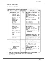
Page 35: ...REV0 10 02 15 H7 2 ...

Page 36: ...REV0 10 02 15 H7 3 7 1 Display Information on Device Operation Click the Scanner Utility as follows Start All Programs HT 4139 Image Scanner Click the Execute button in the Scanner Utility dialog ...

Page 37: ...he number of sheets fed by Pick roller Separator roller Reverse roller will be displayed Pick roller Separator roller Reverse roller NOTE Refer to the Instruction Manual Chapter 2 6 Scanner Utility for the setting of information on the device operation when you replace rollers ...

Page 38: ...gram 1 Start command prompt 2 Execute C OCR32 DIAG32 OCRDMN32_RMT exe 12 1 1 3 Open C OCR32 ETC32 RX8_RMTVER TXT with the Note Pad and confirm Refer to section 7 6 Error Information if you see C OCR32 ETC32 RMTERR TXT Output date and time Version and create date of ROM Version and create date of the flash memory ...

Page 39: ...irmware is correct Load the device unique information after downloading Refer to section 7 6 Error Information if you see C OCR32 ETC32 RMTERR TXT 7 3 Load Save Device Unique Information 7 3 1 Save Device Unique Information save the information into the disk 1 Start command prompt 2 Execute C OCR32 DIAG32 OCRDMN32_RMT exe 12 2 1 C OCR32 ETC32 RX8_U1 OCR Refer to section 7 6 Error Information if yo...

Page 40: ... HT 4139 Image Scanner Scanner Memory Dump Or 1 Start command prompt 2 Execute C OCR32 DIAG32 OCRDMN32_RMT exe 12 3 When the dump information is got OCR8 DMP in the C OCR32 ETC32 folder will be created with the current time when you correct information successfully Refer to section 7 6 Error Information if you see C OCR32 ETC32 RMTERR TXT ...

Page 41: ... if you see C OCR32 ETC32 RMTERR TXT 7 6 Error Information To display the error information Open C OCR32 ETC32 RMTERR TXT with the Note Pad Error Information 1 Error classification code Error Information 2 Error code detected by the systems Error Information 3 File name Key name Not always shown Date of Error Command line Error Message Error Information Function Name ...

Page 42: ... If you only refer to the information click the Exit button If you want to modify the information because of part replacement or other reasons position the cursor to the cell you want to modify and input new data and then click the Update button When you modify data click the Yes button The device will be reset when it finishes successfully Click the OK button in the dialog below The application w...

Page 43: ...information device unique data Information display of Photo Video SW Ultra sonic sensor Display level and status of each items in real time and these will be helpful for failure analysis Mechanical operation Operate mechanical parts such as motors and solenoids Calibration of scanner Get device unique data on photo and optical systems and save them Measurement of USB data transfer rate Measure dat...

Page 44: ...REV0 2010 02 15 H7 11 Select the diagnosis item and click the RUN button Example of Windows XP will be used for following explanation Difference is only layout of screens ...

Page 45: ...1 Skew accuracy measurement 1 Set 10 test sheets 040 7 4 on the input tray and click the RUN button CAUTION MAKE SURE THE ORIENTATION OF THE PAPER IS THE SAME AS THE PICTURE BELOW 2 Click the Yes button 3 Measurement will start ...

Page 46: ...7 Return to the dialog 1 and click the Finish button Fig 1 Position of recognition Display OK passed or NG failed When NG is displayed check below 1 The sheets are normal 2 The rollers are not contaminated 3 If the Pinch Roller is contacting partially 4 Roller wear of the sheet separation mechanism However NG is displayed if more than 80 of the sheets have passed judge it is OK ...

Page 47: ...2 Block accuracy measurement 1 Set 10 test sheets 040 7 4 on the input tray and click the RUN button CAUTION MAKE SURE THE ORIENTATION OF THE PAPER IS THE SAME AS THE PICTURE BELOW 3 Click the Yes button 3 Measurement will start ...

Page 48: ...the Display of calibration information button Fig 2 Position of recognition When NG is displayed check below 1 The sheet is normal Not extended or shrunk 2 The rollers are not contaminated 3 If the Pinch Roller is contacting partially 4 Roller wear of the sheet separation mechanism However NG is displayed if AVR value is within STD judge it is OK ...

Page 49: ...sheets 040 7 4 on the input tray and specify the Scanning mode the Scanning color and the Sheet face for measurement and then click the RUN button CAUTION MAKE SURE THE ORIENTATION OF THE PAPER IS THE SAME AS THE PICTURE BELOW 2 Click the Yes button 3 Measurement will start ...

Page 50: ...nning Normally perform Pencil Red Surface back 7 Click the Finish button to finish Fig 3 Position of recognition In case of NG Check if 1 4 are normal because the results varies depend on 1 Print quality 2 Sheet contamination 3 Accuracy of the block 4 Accuracy of the skew etc Reading position of marks are shown in the Fig 3 If nothing is wrong replace the device because it might be abnormal condit...

Page 51: ...L2 and L3 Check Item Photo Number Criteria Note PC11 20 21 31 41 42 43 51 52 20 F0 PC22 30 FF L3 Blight Level PC22 DBL 30 FF PC11 20 21 31 41 42 43 51 52 00 L2 Dark Level PC22 01 30 PC22 DBL 01 30 If results are out of criteria cleaning and or replacement might be required 7 8 4 2 PC22N PC22 Device unique factor for detection of dual feeding by light intensity NOTE G Gain L1 Blight Level L0 Blight...

Page 52: ...he Ultra sonic sensor Level of the Ultra sonic sensor under various condition Mark Gain Value Sensor Output Sheet Measured Data SS0 0001 same No No Level w o sensor output off set SS1 0001 same Yes No Sensor output SS2 best gain with calibration No No Off set at the best gain SS3 best gain with calibration Yes No Sensor output at the best gain SSP best gain with calibration Yes Yes Sensor output w...

Page 53: ...t the same time to confirm which side has the issue and check if the sheets are normal Repeat scanning multiple times 2 Confirm the images Get images with the reading test of the maintenance menu or Video image display 2 3 Cleaning the optical systems If image is abnormal at 2 clean the lower mirror cover sheet and the scanner assy If result is NG failed 1 Clean the T1 roller Check if there is any...

Page 54: ...actions considering cable disconnection part failure contamination optical axis shift Minimum level is at the gain 00 and it becomes larger in accordance with the gain and maximum is FF If level is not displayed and level will not be changed even lit by flashlight light receiving section has issue If level varies light emitting section has problem 2 Judgment of the photos and switches Switch name ...

Page 55: ...step 4 Sensing direction Y White NOTE Values of the ODD EVN are approximation at each gain at the Video gain All gain the level will not change or if variation is large check the lamp condition If specified step is 0 displayed level maybe about 0020 No output because it locates at the reading position mirror In case of the specified step 4 white with Y position displayed level maybe as shown above...

Page 56: ...ameter and perform this 3 Level of ultrasonic sensor will be displayed every a few second To fix the screen click the Pause button The Pause button will be changed to the FINISH button To finish display click the FINISH button NOTE The ultra sonic sensor detects dual paper feed by checking its level reduced by air layer between papers The level of the ultra sonic sensor is mostly constant Check if...

Page 57: ...Eject All 2 Motor Speed 0 822 0 547 0 411 0 273 m s 3 Operation Mode Continuation interval A interval B 2 If you want to stop operation click the Pause button 3 Click the OK button NOTE Confirm the specified motor is working without any abnormal noise Parameter Operation Stop condition Continuous Continuous rotation mode 10 minutes interval A Repeat 1 second rotation and 0 004 second stop 500 rota...

Page 58: ... button To finish the elevator operation click the FINISH button 1Operation Mode UP DOWN Continuation mode UP F L Position for short feeding H P1 Position for short feeding H P2 2 If you want to stop operation click the Pause button 3 Click the OK button NOTE Check the elevator operation ...

Page 59: ...ify parameters and click the RUN button To finish the elevator operation click the FINISH button 1 Operation Mode A R Continuation A Side R Side 2 If you want to stop operation click the Pause button 3 Click the OK button NOTE Confirm the gate operation ...

Page 60: ...ntinuous feeding Not exists Exists 4 Pause Not exists Exists 5 Lamp mode1 Light on Light off 6 Lamp mode2 Light on Light off default 2 If you want to stop operation click the Pause button 3 Click the OK button NOTE This operation for the overall evaluation of sheet feeding mechanism Sheet size Default A4 Landscape 2970 2100 unit0 1mm The same size as the test sheet Size range that can be specified...

Page 61: ... 4 steps 2 If you want to stop operation click the Pause button 3 Click the OK button NOTE Confirm the mirror motor operation The mirror position is automatically positioned when the power on and located at normal reading position black position Specifying 1 Mirror motor1 surface or Mirror motor2 back 2 White 3 4Step the mirror position at the white position gain measurement of Video amplifier ini...

Page 62: ...REV0 2010 02 15 H7 29 7 8 7 Calibration of Scanner This is the same as OCR Scanner Auto calibration in the chapter 6 ...

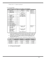
Page 63: ...REV0 2010 02 15 H7 30 ...

Page 64: ...emoval Removing and attaching the cover during maintenance Top Cover Top Cover Washer faced heads screw Unscrew 4 washer faced heads screw as shown in the left picture Slide the Top Cover in direction A Then remove the Top Cover by pulling it in direction B Main Cover L Main Cover L Washer faced heads screw Main Latch Button Push the Main Latch Button to open the Top Cover Unscrew 4 washer faced h...

Page 65: ...de Cover L Washer faced Heads screw Washer faced Heads screw Unscrew 1 bind head screw and 4 washer faced heads screw on the Slide Cover To remove the Side Cover L pull it in the direction of arrow Take the same step as to remove the Side Cover R screw Bind head Back Cover Back Cover Bind head screw Hook Bind head screw Remove the Top Cover Unscrew 3 bind head screws on the Back Cover Slide the Ba...

Page 66: ...rking on the Separator Roller ASSY and the metallic part of the gear face the direction as shown below metallic face side Separator Roller ASSY 5 Separator clutch spacer 88 E_ring TW003 marking side Separator shaft 12 Washer 2 Thrust Washer BLK Thrust Washer BLK 12 Washer 2 88 E_ring TW003 9 Oiles Drymet LF 11 Washer 1 Separator Shaft ASSY Pick Shaft ASSY Replacing the Gear S P For instructions pl...

Page 67: ...aft 7 Pick Gear2 Pick spring Parallel pin 90 E ring TW005 Bind head screw 30 Separator Drive ASSY 45 Pick Motor Belt MXT Belt Remove 2 E rings TW005 and unplug the Separator Drive ASSY from the Separator Drive Shaft and replace Top Gear 2 To attach the Pick Motor Belt the F L Sensor Cable Connector and the Pick Spring For instructions please refer to 9 6 Checking the pressure of the Pick Roller 8 ...

Page 68: ...use errors Read the below warning when going through the procedures If there is an error in the light density check if all procedures were performed correctly Caution Make sure the Fluorescent Lamp and the Lamp Heater are positioned closely The Lamp Heater heats up the Fluorescent Lamp and balances the light density If the 2 are not positioned closely the Fluorescent Lamp will not heat up properly...

Page 69: ...Heater is parallel D good example E bad example Lamp Heater Clip Parallel Uneven Clip Clip Clip Checking the Temperature Fuse Check if the pins 5 A 5 B and 6 A 6 B on connector J73 are maintaining the normal level If the connector is disconnected make sure to replace Lamp ASSY F A Connector J73 6 A 6 B B 5 6 5 A 5 B Specifications Pin Normal Level 1 5 A 5 B Heater Below 100Ω 40Ω 50 2 6 A 6 B Therm...

Page 70: ...SSY Back Loosen 2 washer faced heads screw and pull the Lamp Bracket in the direction shown below Remove the Fluorescent Lamp from the lamp socket Replace the Fluorescent Lamp Caution Do not use force to lift the Fluorescent Lamp To attach the Fluorescent Lamp push in the Fluorescent Lamp and place the Lamp Heater over it If you apply pressure on the tip of the lamp the lamp may get damaged Washe ...

Page 71: ...rors Also attached onto the Lamp Heater is a Temperature Fuse If the Temperature Fuse is disconnected it may cause an error in the light density For instructions please refer to procedure to check if the Temperature Fuse is attached properly Check if the Lamp Heater is attached to 4 metallic clips If it is not attached As shown in exhibit A make sure to attach it to the clips the Fluorescent Lamp ...

Page 72: ...p Clip Clip Checking the Temperature Fuse Check if the pins 5 A 5 B and 6 A 6 B on connector J83 are maintaining the normal level If the connector is disconnected make sure to replace Lamp ASSY F A Connector J83 6 A 6B B 5 6 5 A 6B Specifications Pin Normal Level 1 5 A 5 B Heater Below 100Ω 40Ω 50 2 6 A 6 B Thermostat Below 50KΩ 20KΩ 25 H8 9 ...

Page 73: ...r J21 connecter J3 connected to the Main P K ASSY CP619 P K Connector J3 Push both side of connector and disconnect Connector J2 Push both side of connector and disconnect Connector J21 Lift a little gripping the connector and remove 24 28 25 48 MAIN P K ASSY CPS619 P K 23 DRV P K ASSY CPS614 P K Connector J7 Push both side of connector and disconnect Unscrew 2 bind head screws on the PS ASSY elec...

Page 74: ...Cover FAN J7 Bind head screw Screw loosen a screw Bind head screw loosen a screw Screw Disconnect all 8 connectors attached to MAIN P K ASSY J9 J4 J8 J2 J3 J10 J12 J11 Unscrew 5 bind head screws on the MAIN P K ASSY and remove the MAIN P K ASSY When removing or attaching the MAIN P K ASSY be careful not to damage the parts 24 28 25 48 MAIN P K ASSY CPS619 P K Bind head screw J9 J4 J7 J8 J2 J3 J10 ...

Page 75: ...J34 J32 J38 J33 J26 J25 J24 J23 J22 J36 J20 J27 J28 Unscrew 4 bind head screws and 2 long head screws on the from the DRV P K ASSY CPS614 P K Take the reverse steps to attach DRV P K ASSY CPS614 P K Make sure the FPC cable is attached to the print side of cable facing out and the blue strip end plugs into J20 on DRV P K ASSY CPS614 P K 23 DRV P K ASSY CPS614 P K Bind head screw J31 J26 J25 J24 J23...

Page 76: ...attached to the SS P K ASSY CPS618 P K and remove CPS618 P K Take the reverse step to attach SS P K ASSY CPS618 P K After replacing the SS P K ASSY run the Auto Calibration Test 26 SS P K ASSY CPS618 Tools Needed Magnetic Philips Screwdriver No 2 For instructions please refer to 8 3 41 Mechanism M ASSY Cable Routing MANDATORY Put the removed Mesh cloth on Good Wiring The motor cable is apart from ...

Page 77: ...PS618 P K Plate DRV2 Disconnect 2 connectors J71 J72 attached to the Lamp Inverter Disconnect 2 connectors J101 J102 attached to SS P K ASSY CPS618 P K Disconnect cable from the Clamp When removing the Plate DRV 2 push the cable to the side so it does not get damaged Remove Cover Sheet assembly For instructions please refer to 8 3 14 Replacing the Cover Sheet assembly Remove Lamp ASSY Front For in...

Page 78: ...e Mirror Motor Cable and take the reverse steps to reassemble it To attach the Mirror Motor Connector MMF please read the previous page carefully Attach it straight onto the device Check if the CCB Sensor Connector is attached If it is not attached properly it may cause light density errors Check cable route 8 3 4 and make sure there is enough distance between the Motor Cable and the Ultra Sonic S...

Page 79: ...push it in the direction of the arrow then screw the screws Bind head screw Bind head screw SS Sensor ASSY Receptor SS Sensor ASSY Receptor 35 Main Button ASSY Unscrew 1 bind head screw on the Ultra Sonic ASSY Transmitter and remove the Ultra Sonic ASSY Transmitter Remove the cable inside the Ultra Sonic ASSY Transmitter Disconnect and replace the connector attached to the SS Sensor To attach the ...

Page 80: ... Loosen 1 bind head screw on the Hopper ASSY Lift the Hopper ASSY and pull out the Hopper ASSY Take the reverse steps to attach the Hopper ASSY When screwing the bind head screws make sure the Hopper ASSY is attached horizontally Be cautious of the position of the Elevator Arm Washer Faced heads screw Bind Head screw screw down Hopper Cover 27 Hopper ASSY ...

Page 81: ...er countersunk screws ツメ 31 A Stacker Unscrew 3 countersunk screws from the R Stacker Remove the Stacker by pulling it up Loosen 1 bind head screw on the Stacker Guide and remove the Stacker Guide To remove the A Stacker remove the R Stacker first To attach the stackers take the reverse steps Stacker Guide ...

Page 82: ...nect the MRB connector and then the Imprinting Head Assembly 17 Imprinting Head Assembly Bind head screw Bind head screw MRB Connector Unscrew 2 bind head screws on the Ribbon Holder When replacing the Imprinting Head bend the tip lightly in the direction of the arrow shown in the below picture Replace Imprinting Head Read 9 7 Adjusting the Ribbon Holder and check the Ribbon Holder and the positio...

Page 83: ...he Scanner ASSY and disconnect the CCD Sensor Connector J40B and the Mirror Motor connector from the Scanner ASSY To attach the Mirror Motor Connector MMF please read the previous page carefully Attach it straight onto the device Check if the CCB Sensor Connector is attached If it is not attached properly it may cause light density errors Take the above steps to attach the Scanner ABBY After repla...

Page 84: ... cable route 8 3 4 and make sure there is enough distance between the Motor Cable and the Ultra Sonic Sensor Cable Noise between the 2 parts could cause errors in the Ultra Sonic Sensor 8 3 12 Replacing the Lamp Inverter Back Tools Needed Magnetic Philips Screwdriver No 2 64 LAMP INVERTER Bind head screw Bind head screw Connector J82 Connector J81 Remove Side Cover L R and Back Cover For instructi...

Page 85: ...Main Cover L For instructions please refer to 8 1 Preparation Slide and pull the Lower Mirror ASSY Take the reverse steps to attach the Lower Mirror ASSY 40 Lower Mirror ASSY Remove the Side Cover L For instructions please refer to 8 1 Preparation Slide and pull the Lower Mirror ASSY Take the reverse steps to attach the Lower Mirror ASSY ...

Page 86: ...old the Cover sheet with your right hand and use your left finger to slide the sheet in the direction of the arrow Take the reverse step to attach the Cover sheet 16 Cover Glass ASSY Removing the Cover Glass Slide the Cover glass assembly with your left finger in the direction of the arrow Take the reverse step to attach the Cover glass ...

Page 87: ...rews on the Front Guide and remove Front Guide Bind head screw Connector PC11 Front Guide Bind head screw Remove the Guide Lower Mirror the Cover Glass ASSY For instructions please refer to 8 3 14 Replacing the Cover glass assembly Unscrew 5 bind head screws on the Lower Guide ASSY Disconnect connector PC22 Disconnect connectors 20L PC21 and PC31 Remove Lower Guide ASSY from the device side view s...

Page 88: ...1 tension of the Motor Belt Side view Left T1 Motor adjustment screw 46 MXT Belt Remove the Stopper Ring from the T1 Driver Roller Slide it to the right and remove it Side view Left 90 E_Ring TW005 67 Drive Roller M Take the reverse step to attach the Motor For instructions please refer to Chapter 9 1 tension of the Motor Belt ...

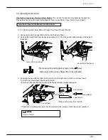
Page 89: ...REV0 10 02 15 H8 26 ...

Page 90: ...ad screws on the Front Guide and remove the Front Guide Bind head screw Bind head screw Connector PC11 Front Guide Remove the Reverse Roller ASSY by lifting the Reverse Roller ASSY Unscrew 2 bind head screws on the Reverse ASSY Slide the Reverse ASSY to the right and rotate the device to remove Reverse ASSY 13 Reverse ASSY Bind head screw Bind head screw PC21 Connector Lower Guide ASSY 29 Reverse ...

Page 91: ...REV0 10 02 15 H8 28 Take the reverse steps to attach the Reverse ASSY After replacing the Reverse ASSY For instructions please refer to 9 4 Checking the Reverse Roller Pressure and check the pressure ...

Page 92: ...er open Unscrew and replace 2 bind head screws on the Slide Plate ASSY 95 Slide Plate ASSY Bind head screw 8 3 18 Replacing the Main Button Tools Needed Magnetic Philips Screwdriver No 2 Remove the Main Cover L the Side Cover L For instructions please refer to 8 1 Preparation Unscrew and replace 2 bind head screws on he Main Button ASSY 35 Main Botton ASSY Bind head screw Replace the Main Latch R ...

Page 93: ...or instructions please refer to 8 1 Preparation Keep the Top Cover open Unscrew the bind head screw on the Latch hook MF ASSY and Latch hook MR ASSY 94 Latch hook MR ASSY 93 Latch hook MF ASSY Bind head screw Bind head screw grease After replacing the parts please refer to 9 2 Checking the Upper Guide Gap to check and adjust the location of the Latch hook ...

Page 94: ...or J7 Disconnect connector J10 attached on the MAIN P K ASSY Connector J10 BLACK should be under Connector J7 24 25 MAIN P K ASSY CPS619 P K Unscrew 4 bind head screws on the Eject Guide and remove the Eject Guide for instructions please refer to 8 3 5 Replacing the Scanner ASSY Remove 2 plastic rivets as shown below Remove the Panel from the countersunk Take the reverse steps to attach the Counte...

Page 95: ...ide Remove PC11L L ASSY Disconnect the sensor from connector Remove the sensor Remove the clips attached to the Sensor PC11 Sensor Side and remove the Sensor Remove the clips attached to the Photo Micro Sensor ASSY L L Sensor and remove the Photo Micro Sensor ASSY Attach new Sensors Take the reverse steps to attach the Sensor When you install the PC11LL ASSY refer to the photo below After replacin...

Page 96: ...w 5 bind head screws from the Lower Guide ASSY For instructions please refer to 8 3 15 Replacing the Drive Roller Disconnect the sensor from the middle connector Remove the sensor from the device Unscrew 1 countersunk screw from the Lower Guide ASSY and remove the Sensor Emission Unscrew 1 hexagonal screw from the Lower Guide ASSY and remove the Reflection Sensor and the Main Cover L ASSY K Unscre...

Page 97: ...o attach the Sensor After replacing the part run Auto Calibration Test hexagonal screw 55 Sensor PC52 Emission Hook Replacing the Reflection Sensor PC42 Tools Needed Magnetic Philips Screwdriver No 2 Remove the Top Cover the Main Cover L R the Side Cover L R and the Back Cover For instructions please refer to 8 1 Preparation Disconnect the Reflection Sensor from the middle connector then unscrew 1...

Page 98: ... After replacing the part run Auto Calibration Test hexagonal screw 56 Reflection Sensor PC43 57 Prism PC42 hexagonal screw Replacing the Sensor PC52 Emission Tools Needed Magnetic Philips Screwdriver No 2 Remove the Top Cover the Main Cover L R the Side Cover L R and the Back Cover For instructions please refer to 8 1 Preparation Disconnect the sensor from the middle connector then unscrew 1 hexa...

Page 99: ...he part run Auto Calibration Test hexagonal washer Pinch Roller ASSY Eject Guide ASSY Washer faced Heads screw 57 Prism PC41 Replacing the Sensor PC51 Emission Tools Needed Magnetic Philips Screwdriver No 2 Remove the R Stacker For instructions please refer to 8 3 8 Replacing the Stacker Unscrew 1 hexagonal washer faced head screw attached to the Sensor PC51 and disconnect the connector from the S...

Page 100: ...ad screw Bind head screw Bind head screw Remove the Sensor Unscrew 1 hexagonal screw on the Prism PC21 Sensor and remove the Prism PC21 Sensor Disconnect the connector on PC22 ASSY PC22 Sensor from the middle connector Unscrew 1 countersunk screw from the Upper Guide ASSY and remove the PC22 ASSY PC22 Connector Unscrew 1 hexagonal screw on the Prism PC31 Sensor and remove the Prism Attach the new ...

Page 101: ...crews on the Ultra Sonic Sensor Unscrew 4 bind head screws on the M2 ASSY Cover then remove the M2 ASSY Cover M2 ASSY Cover Bind head screw Bind head screw Bind head screw Bind head screw Unscrew 2 screws on the D1 Pinch Roller and remove the Pinch Roller Remove the Sensor Flip the M2 ASSY Cover and remove the clips on the Sensor PC11 Sensor and remove the Sensor Flip the M2 ASSY Cover and remove ...

Page 102: ...reparation Disconnect the G SOL connector Unscrew 1 screw between the R SOL ASSY and the Gate Shaft Unscrew 1 screw from the bottom of the R SOL ASSY Replace the R SOL ASSY and push the Gate Shaft down and screw 1 screw Connect the G SOL ASSY 53 R_SOL ASSY SCREW 37 Gate Shaft PUSH SCREW SCREW 53 RSOL ASSY 37 Gate Shaft ASSY SCREW G_SOLConnector x PUSH POINT ...

Page 103: ...Main P K ASSY CPS619 P K Remove the DRV P K ASSY CPS619 P K When replacing the Gas Spring on the right side of the device For instructions please refer to 8 3 3 Replacing the DRV P K ASSY CPS614 P K Unscrew 4 bind head screws from the PK BOX ASSY and slide it towards you PK BOX ASSY Bind head screw Bind head screw Bind head screw Bind head screw Remove 2 Stopper E Rings TW007 and replace the Gas S...

Page 104: ... the Main Cover the Side Cover L R and the Back Cover For instructions please refer to 8 1 Preparation Disconnect the Connector Unscrew 2 bind head screws from the Stepping Motor and remove the Stepping motor from the device Bind head screw Earth Connector nect Bind head screw 41 Stepping Motor Unscrew 2 screws from the Anti vibration rubber and replace the stepping motor screw 42 Anti vibation ru...

Page 105: ...move it from the device Unscrew 2 bind head screws from the Reverse ASSY and slide the Reverse ASSY to the right Rotate the Reverse ASSY and remove it from the device For instructions please refer to 8 3 16 Replacing the Reverse ASSY Lift the Soft Absorber up and remove it from the device Put the spring attached to the old Soft Absorber onto the new Soft Absorber Take the reverse steps to attach t...

Page 106: ...tion Remove the Gear ELE Shaft from the device For instructions please refer to 8 3 28 Replacing the Gear ELE Shaft Remove the Parallel Pin from the device and remove the E Ring TW005 Stopper on the left and right side Remove the Elevator ASSY from the device Take the reverse step to attach the Elevator ASSY 32 Elevator ASSY 65 Gear ELE Shaft 90 E ring TW005 Parallel Pin 90 E ring TW005 ...

Page 107: ... SOL ASSY Remove the E Ring TW005 Stopper and remove the Gate Shaft ASSY Take the reverse step to attach the Gate Shaft ASSY 37Gate Shaft ASSY 90 E ring TW005 Bind head screw 8 3 28 Replacing the Gear ELE Shaft Tools Needed Magnetic Philips Screwdriver No 2 E ring Removal Remove the Side Cover L R For instructions please refer to 8 1 Preparation Remove the E Ring TW004 Stopper and remove the Gear ...

Page 108: ...ewdriver No 2 Open the Pick U Cover and remove the Pick Unit ASSY from the device Unscrew 2 bind head screws and remove the T1 Pinch Roller ASSY from the device Take the reverse steps to attach the T1 Pinch Roller ASSY 71 Pick U Cover Bind head screw 92 T1 Pinch Roller ASSY Bind head screw 92 T1 Pinch Roller ASSY ...

Page 109: ...e device For instructions please refer to 8 3 22 Replacing the R SOL Take the reverse step to attach the 2GT Pulley 50 2GT Belt 89 E ring TW004 81 2GT Pulley 18 Washer 81 2GTPulley 18 41 Eject Motor 80 2GTPulley 36 53 R_SOL ASSY 8 3 32 Replacing the MXL Belt Tools Needed Magnetic Philips Screwdriver No 2 E ring Removal Remove the Main Cover L R For instructions please refer to 8 1 Preparation Remo...

Page 110: ...d the gears Take the reverse steps and attach the Ribbon Holder onto the device Check cable route 8 3 4 and make sure there is enough distance between the Motor Cable and the Ultra Sonic Sensor Cable Noise between the 2 could cause errors in the Ultra Sonic Sensor To adjust the Imprinting Gap please refer to 9 5 Adjusting the Imprinting Gap Run the print test and check the printing condition Bind ...

Page 111: ...eplacing the Scanner ASSY and make the scanner in the same state as the picture below Unscrew 2 screws on the DC Fan and disconnect the connector J7 Remove the DC Fan from the device Take the reverse steps to attach the DC Fan Check cable route 8 3 4 and make sure there is enough distance between the Motor Cable and the Ultra Sonic Sensor Cable Noise between the 2 could cause errors in the Ultra S...

Page 112: ...structions please refer to 8 3 8 Replacing the Stacker Unscrew 4 bind head screws on the Stacker Back Guide R Remove and replace the Anti Static Guide from T11 Guide A ASSY Take the reverse steps to attach the Anti Static Guide 62 Anti static brush Stacker Bck Guide R Bind head screw T11 Guide A ASSY Bind head screw Bind head screw Bind head screw Replacing the Anti Static Brush on the Lower Guide...

Page 113: ... please refer to 8 3 7 Replacing the Hopper ASSY Unscrew 2 bind head screws from the Front Guide and remove the Front Guide Bind head screw Bind head screw Connector PC11 Front Guide Use the Driver and remove the Reverse Cover ASSY as shown below To attach the Reverse Cover ASSY insert part A and slide part B in the direction of the arrow shown below A B 70 Reverse Cover ASSY ...

Page 114: ...the Separator Shaft ASSY For instructions please refer to 2 7 2 Replacing the Pick Roller and the Separator Roller Replace the Gear S P on the Pick Top Cover taking the steps below Put grease on the A part as shown below Warp of this direction A is Not good Warp of this direction B is OK Check flatness with a scale A CAUTION When attach the Gear S P not open the Pick Top Cover unnecessarily 103 Pi...

Page 115: ...acket Do not pull hard to remove the F L Bracket ASSY The F L Sensor Cable is routed onto the F L Bracket ASSY Disconnect the connector from the F L Sensor Cable Unscrew 1 screw from the countersunk FL and remove the F L Sensor Take the reverse steps to attach the F L Sensor Plate FL Pick U Cover Bind head screw F L Sensor F L Sensor Cable F L Sensor Connector F L Sensor Hook Screw 58 F L Sensor P...

Page 116: ...lan when Replacing the Scanner ASSY M1 ASSY Cover Motor Cable CAUTION Check cable route 8 3 4 and make sure there is enough distance between the Motor Cable and the Ultra Sonic Sensor Cable If not the Ultra sonic Sensor might not work correctly because of noise 64 LAMP INVERTER 26 SS P K ASSY CPS618 P K SS Sensor Cable ...

Page 117: ...N Adjust the tension by screw σ Direction of pressing Tension Roller 49 MXL Belt EJECT Screw for adjustment 41 MOTOR ASSY EJECT ℴ 2mm P 0 9 2 1N Adjust the tension by tension roller P σ Side view Side view Side view Side view Right Right Right Right 50 2GT Belt BRAKE Screw for adjustment 44 MOTOR ASSY BRAKE Tools Needed Magnetic Philips Screwdriver No 2 Tension Gauge ...

Page 118: ...Main Motor ℴ 2mm P 0 9 2 1N Adjust the tension by screw Side view Side view Side view Side view Right Right Right Right σ 46 MXL Belt T1 47 MXL Belt MAIN 41 MOTOR ASSY T1 41 MOTOR ASSY MAIN Direction of pressing Direction of pressing Screw for adjustment Screw for adjustment ...

Page 119: ... Hook Holder Top Take the same step for the opposite side Upper Guide Measurement point Bump of Lower Guide 94 Latch hook MR ASSY Upper Guide Screw for adjustment σ 93 Latch hook MF ASSY Hook holder top Screw for adjustment Top Guide Bump of Eject Guide Side view Side view Side view Side view Right Right Right Right Side view Side view Side view Side view Left Left Left Left Side view Side view Si...

Page 120: ...he interlock Attach the Interlock Switch Interlock Switch Part ℴ 0 4 0 9mm 15 Cover Sheet ASSY 40 Lower Mirror ASSY Main Base L Measure with the thickness gauge Main Base R Side view Side view Side view Side view Left Left Left Left Roller Inter Lock Switch ASSY 59 INL_ASSY Side view Side view Side view Side view Left Left Left Left Inter Lock Switch Screw for adjustment Tools Needed Magnetic Phil...

Page 121: ...s shown below The distance from the Dust Cover and the Reverse Arm ASSY should be 31mm This position will be defined as Pressure P The Measured Load will be Pressure P 3 5 0 25N 350 25g f the result is outside the appropriate measurement adjust the position of the knob A 2mm shift in the knob will change 0 5N Adjust screw Tension Gauge Strong Weak Pressure position 31mm Reverse Roller ASSY End fac...

Page 122: ...o adjust it After attach the LL washer head on the Imprinting Head ASSY Use the thickness gauge and measure the gap between the Imprinting Head and the Roller It should be 0 2 0 35mm If the gap is outside that boundary adjust the knob on the Imprinting Head Replacing the Imprinting Head Check whether the center of the Imprinting Head ASSY should be leaning towards the left and loosen 2 bind head s...

Page 123: ...ure the load when the Roller is parallel The measured load shall be the following value Standard Specification 1 2 0 2N By adjusting the position of the hook on the Pick Spring you can change the pressure on the Pick Roller Shifting one hole will change 0 4 N Point If misfeed errors keep occurring adjust the hook position so that stronger pressure is applied Sector Form Tension Gauge 28 Pick unit ...

Page 124: ... screws on the Ribbon Holder and remove the Ribbon Holder Loosen 2 bind head screws on the DC Motor and attach the DC Motor by applying pressure in the direction of the arrow 108 DC Motor Bind head screw x2 Ribbon Holder 108 DC Motor Bind head screw x2 106 Gear NMB Ribbon Holder Tools Needed Magnetic Philips Screwdriver No 2 ...

Page 125: ...screws If the Ribbon Cassette is loose bend the hinge slightly inwards as shown in the picture below Holding section Make sure the Ribbon Cassette is firmly inserted into the Ribbon Holder Important Make sure the Gear is positioned in the middle of the Ribbon Holder Ribbon Holder Hole 106 Gear NMB ...

Page 126: ...e value 10g 0 1N Range of use 100 400g 1N 4N 6 Metric Ruler 150mm Adjust reverse roller Minimum scale value 1mm Range of use 0 40mm 0 20mm 0 30 0 35 Platen gap 7 Thickness gauge 0 40mm 0 45 0 50 0 60 0 70 0 80 0 90 1 00 Adjust head gap 8 Absolute Ethanol NA Cleaning 9 Gauze Cleaning cloth NA Cleaning 10 Digital Voltage Meter AC100 300V Confirm power supply voltage Confirm temp fuse of lamp 11 Test...

Reviews: