


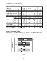
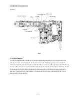
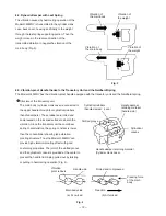
Summary of Contents for H45MRY
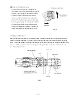
Page 36: ......
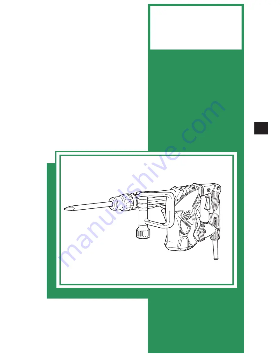
The Hitachi H45MRY is a powerful and versatile tool designed to effortlessly handle heavy-duty tasks. Unlock its true potential with the detailed Handling Instructions Manual available for free download from manualshive.com. A comprehensive manual that will guide you through every step to ensure optimal performance and safety.
Page 36: ......


