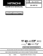
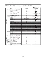
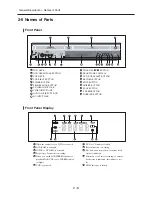
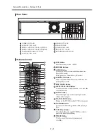
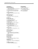
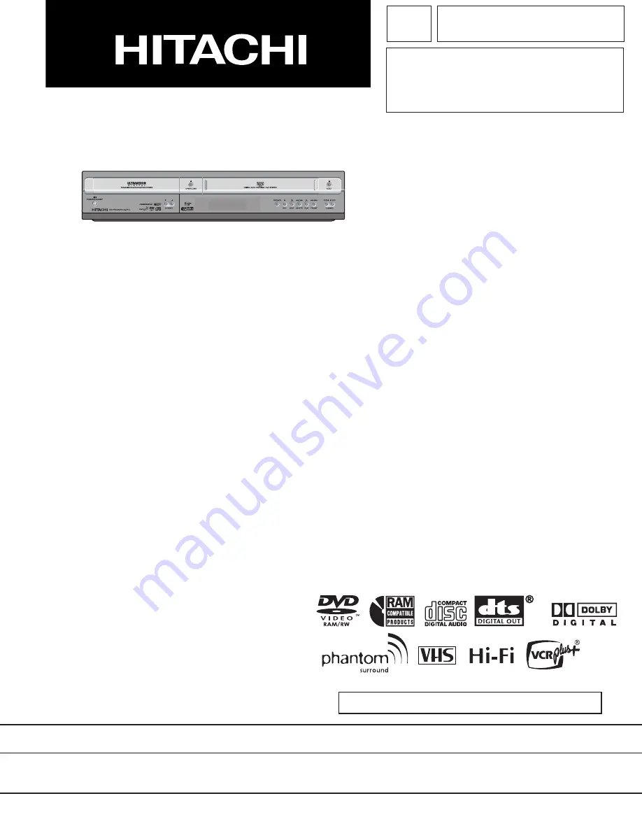
Hitachi DV-RF7U, Service Manual
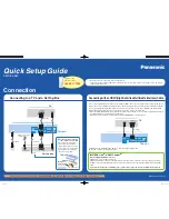
The Hitachi DV-RF7U is a versatile and user-friendly device, designed to enhance your entertainment experience. With its sleek design and advanced features, this user-friendly device is perfect for recording and playing your favorite videos. Ensure optimal usage by downloading the free Service Manual from manualshive.com.
Share
Download
Reviews:
No comments
Related manuals for DV-RF7U
DIGA DMR-ES15
Brand: Panasonic Pages: 2
Diga DMR-EH55
Brand: Panasonic Pages: 2
Diga DMR-EZ28
Brand: Panasonic Pages: 2

Diga DMR-ES10EB
Brand: Panasonic Pages: 6
Diga DMR-ES20DEB
Brand: Panasonic Pages: 6
Diga DMR-EZ27EB
Brand: Panasonic Pages: 2
Diga DMR-EZ17
Brand: Panasonic Pages: 2
Diga DMR-ES35V
Brand: Panasonic Pages: 2
Diga DMR-ES30V
Brand: Panasonic Pages: 2
Diga DMR-ES40V
Brand: Panasonic Pages: 4
Diga DMR-EX75EB
Brand: Panasonic Pages: 4
Diga DMR-EZ48V
Brand: Panasonic Pages: 2
Diga DMR-EZ37
Brand: Panasonic Pages: 8
Diga DMR-EZ45VEBS
Brand: Panasonic Pages: 4
DMR-EX75
Brand: Panasonic Pages: 4
DMR-ES36V
Brand: Panasonic Pages: 2
DMREA38V - DVD RECORDER - MULTI LANGUAGE
Brand: Panasonic Pages: 2
Diga DMR-EZ27
Brand: Panasonic Pages: 8


