background image

Operating Guide

Model Name

UT32X812

Record the serial number of your monitor for future reference.

SERIAL NO.                                                            

This serial number is located on the back and right side of the monitor.

If you have a question about this product please call 800-Hitachi for assistance

READ THE ENCLOSED INSTRUCTIONS CAREFULLY.
KEEP THIS OPERATING GUIDE FOR FUTURE REFERENCE.

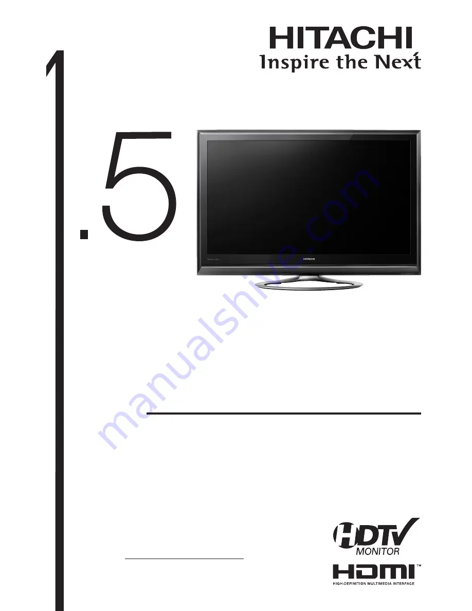
Hitachi Director’s Series® HDTV Monitor

1.5™ UltraThin LCD HDTV Monitor
32” Class (31.51" Diagonal)
Black Sapphire Crystal Frame
1366 x 768p 120 Hz,  PictureMaster™ V
(1) HDMI

 (V.1.3 with CEC) Input; (1) RGB D-sub15 Input with Audio

Summary of Contents for Director's UT32X812

Page 1: ... you have a question about this product please call 800 Hitachi for assistance READ THE ENCLOSED INSTRUCTIONS CAREFULLY KEEP THIS OPERATING GUIDE FOR FUTURE REFERENCE Hitachi Director s Series HDTV Monitor 1 5 UltraThin LCD HDTV Monitor 32 Class 31 51 Diagonal Black Sapphire Crystal Frame 1366 x 768p 120 Hz PictureMaster V 1 HDMI V 1 3 with CEC Input 1 RGB D sub15 Input with Audio ...

Page 2: ...e Power Plug into the Wall Socket 21 BASIC OPERATION 22 Power On Off 22 Volume Up Down 23 Mute 23 Input Switching to HDMI and RGB 24 Input Signal Screen Display 24 SETUP OPERATION 25 How to Use the Remote to Control your External Devices 25 How to Use the Macro Buttons 29 How to Use the Learning Option of the Remote Control 30 Remote Control Codes 31 How to Use the On Screen Display OSD System 33 ...

Page 3: ...an electrician for replacement of the obsolete outlet Protect the power cord from being walked on 10 or pinched particularly at plugs convenience receptacles and the point where they exit from the apparatus Only use the attachments accessories specified by 11 the manufacturer Use only with the cart stand tripod 12 bracket or table specified by the manufacturer or sold with the apparatus When a car...

Page 4: ...ion If this equipment does cause harmful interference to radio or television reception which can be determined by turning the equipment off and on the user is encouraged to try to correct the interference by one or more of the following measures If the Monitor is connected with a Set Top Box or TV Receiver reorient or relocate the receiving antenna Increase the separation between the equipment and...

Page 5: ...ny loss damage or injury as a result of misuse Reproduction copying utilization modification and or transmission in whole or in part of this manual are prohibited except by prior written consent All other products and company names used in this manual are trademarks or registered trademarks of their respective owners Trademark Credits VGA and XGA are trademarks of International Business Machines C...

Page 6: ...ts are clearly indicated in or adjacent to an illustration the symbol to the left indicates that the power plug should be disconnected from the power outlet WARNING There is a risk of fire electric shock or serious injury If serious problems occur unplug the power cord immediately Serious problems such as Smoke abnormal odor or noise emitted from the product No picture no sound or distorted pictur...

Page 7: ... the power cord Do not damage modify twist forcibly bend heat or pull excessively on the power cord Do not place heavy objects including the unit itself on top of the power cord If the power cord is damaged contact 800 HITACHI for repairs or exchange Use only with designated power supply voltage To prevent the risk of fire and electric shock operate the product only with the power supply voltage i...

Page 8: ...uld cause partial discoloration or blurring of the image on the CRT based television Please install it away from the speakers of the unit Disconnect all of the external connection cables and detach the anti tumble measures before moving the unit Otherwise fire electric shock or personal injury may result Connect the power plug securely Improper connection will cause overheating and may result in f...

Page 9: ...es or cordless headphones may not operate properly around the unit This is because of communication failure Please note that this is not a malfunction When you dispose of the product at the end of its service lifetime follow the regulations in your residential area For more information contact the local authority or the dealer where you purchased the product Cleaning and Maintenance Please make su...

Page 10: ...e unit in order to avoid increasing the internal temperature Make sure not to block any ventilation holes Do not install the unit in a small space such as inside a cabinet closet or box without adequate ventilation Leave at least 10cm 4 of clearance from each side of the unit and 30cm 1 from the top of the unit to ceiling Securing to a table Securing to ceiling or wall Use the specified mounting u...

Page 11: ...panel displays on furniture that can easily be used as steps such as a chest of drawers Remember that children can become excited while watching a program especially on a larger than life flat panel display Care should be taken to place or install the display where it cannot be pushed pulled over or knocked down Care should be taken to route all cords and cables connected to the flat panel display...

Page 12: ...s They may be used for the Wall Mount installation CAUTION Please make sure screws are tightened properly The torque should be 1 8 3 0 N m 18 30 kgf cm WARNING Remove the 4 screws and raise straight up from tabletop stand Screw Mounting Holes 4 places Don t use the original flat head screws A that comes in the monitor for the Wall Mount Braket The length is not long enough Wall Mount Brackets Scre...

Page 13: ...nued Floor Stand Setup 2 Remove the 4 screws and raise straight up from tabletop stand CAUTION Keep the screws They will be used for the Floor stand installation Monitor About the Installation This product is heavy and should be carried by at least 2 people For Stand Assembly please refer to the Installation Manual of the Floor Stand AS LSZ0081 or AS LSZ0082 Screws from the tabletop stand Please m...

Page 14: ...ferent from that depicted Connection 18 21 q Connect the power cord to the rear panel w Connect to external equipment Example 1 Connecting to PC To insert D sub 15 pin tilt the monitor forward and bring the terminals into view Two people are required to hold the monitor and insert D sub 15 pin safely Be careful not to damage the panel D sub 15 and Audio cables are not included Example 2 Connecting...

Page 15: ...Power On Off button on the remote control If no equipment is connected to the Monitor the color of the indicating lamp turns to Orange and the Illumination Lamp turns off indicating Power Save Mode Language Selection The initial language setting for on screen displays is English US You can change to your preferred language q Press the button to display Main Menu w Select Language using the button ...

Page 16: ...OK button Menu Exit button q Power Cord Socket w HDMI Input Terminal Please refer to 18 21 for detailed information regarding the connections q w e r t y u i Main Power switch o Service use only a RS232C s PC RGB DVI Analog Audio Input Terminal d PC Connection Terminal D sub 15 Pin f Reset button See 46 i o a s d h j k g l Control panel located on the bottom INPUT AV4 AUDIO VIDEO S VIDEO HDMI 3 R ...

Page 17: ...ONTROL BUTTONS DVD PVR VCR AVR Control the functions of your DVD and VCR Device Buttons TV DVD PVR VCR SAT CBL AVR Press these buttons to switch between your devices Numeric Buttons TV DVD PVR VCR SAT CBL AVR Press these buttons to manually enter the channel and for numeric entry when navigating through the OSD menu system Enter Button TV DVD VCR SAT CBL Press this button to use as a SELECT featur...

Page 18: ...fect the remote control Do not spill water or any liquid on the remote control Do not place the remote control on a wet surface Do not place the remote control under direct sunlight or near sources of excessive heat Use the remote control within a distance of about 5m 16 from the front of the unit s remote control sensor and within an angle of about 30 degrees on both sides Handling the Remote Con...

Page 19: ... attach the supplied cushion around the HDMI cable when connecting See 20 Information The HDMI High Definition Multimedia Interface is a multimedia I O Input Output interface Only one cable is used to transmit all video audio control signals thus facilitating easy connection Moreover the digital signals can produce high quality data without any degradation If your external device has an HDMI termi...

Page 20: ...ally turned On and switches the picture and audio to HDMI input On System Standby Off Condition while the monitor is On When the monitor is switched off or set to Standby mode the connected equipment is also turned off or in Standby mode On AV Center Control Off Selecting On will activate AV Center OSD interface in case you purchased the optional Hitachi A V Center On Connecting to Equipment Havin...

Page 21: ...und the HDMI cable so as not to leave any clearance Cushion supplied accessory HDMI cable CONNECTION continued 2 Connect your Equipment to the Monitor continued Connecting to a PC The PC connection terminal D sub 15 pin the PC RGB DVI Analog Audio Input terminal are connected to the PC allowing an analog RGB signal NOTE About the connection of D sub 15 pin see 13 for details IN OUT AUDIO or Exampl...

Page 22: ...e other than that indicated AC120 60Hz It may cause fire or electric shock For the LCD monitor a three core power cord with a ground terminal is used for efficiency protection Always be sure to connect the power cord to a three pin grounded outlet and make sure that the cord is properly grounded If you use a power source converter plug use an outlet with a ground terminal and screw down the ground...

Page 23: ...n Off by pressing the Power On Off button on the remote control The Indicating Lamp Illumination Lamp Status Indicating Lamp Illumination Lamp Power Status Remark Off Off Red Standby mode Green Blue On Orange Power Save mode Refer to 44 and 45 for the condition Blinking Green Blue On Receiving Remote Control signal NOTE If the image does not appear on the screen at all or if there is any problem w...

Page 24: ... will shift to the left Mute 1 To mute sounds press the button on the remote control The sound of the unit is temporarily turned Off The color of the Volume Indicator will turn into grey while muting the volume 2 To turn the sound back on press the button again or press the Volume Up button on either the remote control or control panel The color of the Volume Indicator will turn back to blue NOTE ...

Page 25: ...nal Screen Display The input signal status can be displayed on the screen by pressing the button on the remote control The display will go out in approximately 6 seconds HDMI DVI 720p Input mode Signal mode HDMI DVI connection only HDMI mode Composite Composite mode RGB H 48 4kHz V 60 0 Hz Input mode Input horizontal frequency Input vertical frequency RGB mode INFO button Input Select NOTE Switchi...

Page 26: ... is entered When this occurs the remote control is programmed for your cable box If the cable box does not turn off try a different four digit preset code The remote will now control your Cable box 7 Repeat the same procedure for your set top box or satellite receiver select SAT CBL your DVD select DVD your VCR PVR select VCR PVR or your AVR select AVR NOTE If your external device cannot be operat...

Page 27: ...Macro Keys Last CH EXCLUSIVE TV mode Monitor buttons These buttons are for operating the TV P Mode HDMI Input Aspect Vol Up Down RGB Mute MY SET TOP BOX SATELLITE RECEIVER CODE IS ____________________ NOTE Refer to the operating guide of the Set Top Box Satellite Receiver for operation of the buttons exclusively for the Set Top Box Satellite Receiver PRECODED SET TOP BOX SATELLITE buttons These bu...

Page 28: ...enu Info Return Number PAD EXCLUSIVE TV mode Monitor buttons These buttons are for operating the TV P Mode HDMI Input Aspect Vol Up Down RGB Mute MY VCR PVR CODE IS ____________________ NOTE Refer to the operating guide of the VCR PVR for operation of the buttons exclusively for the VCR PVR PRECODED VCR PVR buttons These buttons transmit the chosen precoded VCR PVR codes Power Cursor OK Record Men...

Page 29: ...___________ NOTE Refer to the operating guide of the AVR for operation of the buttons exclusively for the AVR PRECODED AVR buttons These buttons transmit the chosen precoded cable codes Power Channel Up Down Input Number PAD Vol Up Down Mute Cursor PAD Menu Return EXCLUSIVE TV mode buttons These buttons are for operating the TV P Mode HDMI Info Aspect RGB ...

Page 30: ...eady if not please try again step 2 Select one of the Macro keys M1 M2 M3 M4 that the 4 Macro will be setup on Enter the key sequence that the Macro steps will include 5 up to 10 keystrokes per Macro To enter a delay between steps the user should press the current mode button TV DVD PVR SAT AVR After all macro steps are entered press the same Macro 6 key that was pressed M1 M2 M3 M4 The remote wil...

Page 31: ...LED 7 will blink twice and turn off The remote will stay in learn mode return to step 4 If the code is not learn successfully the respective mode LED will blink for 1 second and you will have to return to step 4 In order to exit the learning process press and hold 8 the Mode key for 3 seconds LEARNING SETUP EXAMPLE Learn AUDIO language key from a DVD player Press and hold DVD mode on the R C Enter...

Page 32: ... 0121 EMEREX 0032 EMERSON 0037 0184 0240 0000 0121 0043 0209 0002 0278 0479 1593 FISHER 0039 0047 0000 0104 0046 FUJI 0035 0033 FUJITSU 0000 FUNAI 0037 0000 0072 0278 1593 GARRARD 0000 GATEWAY 1972 GE 0060 0035 0048 0240 0000 0065 GEMINI 0060 GENEXXA 0037 0000 0278 GO VIDEO 0240 0432 0526 0614 GOLDSTAR 0035 0037 0039 0000 0278 0038 GOODMANS 0037 0081 0000 0072 0278 GRADIENTE 0000 GRANADA 0081 0042...

Page 33: ...65 ONKYO 0503 0627 1769 OPPO 0575 1224 1525 2185 OPTIMUS 0571 PALSONIC 0672 0852 PANASONIC 0503 0490 0571 0703 1641 1762 PHILCO 0675 PHILIPS 0503 0539 0646 0675 1267 1340 1354 2056 2084 PIANODISC 1024 PIONEER 0525 0571 0142 0631 1571 POLAROID 1020 1061 1086 POLK AUDIO 0539 PORTLAND 0770 PRESIDIAN 0675 PRIMA 2126 2127 PROCEED 0672 PROSCAN 0522 PROVISION 0778 RADIONETTE 0741 RADIOSHACK 0571 RCA 0522...

Page 34: ... press the or the button NOTE The OSD menu screen will be closed automatically when no operation has been made for about one minute If the item on the menu is shown in gray it means that it cannot be selected or adjusted Select Language Select the language from the list so that the OSD menu can be displayed in the selected language The default setting is English US How to set Language 1 Enter the ...

Page 35: ...set each item on the menu screen to the factory setting 40 Audio Treble Adjust to increase or decrease the level of treble 15 15 Bass Adjust to increase or decrease the level of bass 15 15 Balance Adjust the balance of sound from the bottom right and left speakers 10 10 Surround Select surround sound Off On Bass Boost Enhance bass sounds Off On Clear Voice Select clearer and more realistic sounds ...

Page 36: ...er normal conditions Brightness 31 31 Adjust brightness according to personal preference by using the button Color 31 31 Adjust color according to personal preference by using the button Sharpness 15 15 Preferred sharpness can be adjusted by pressing the button for softer image or the button for sharper image Tint 31 31 Pressing the button enhances red and weakens green while pressing the button w...

Page 37: ...t and color blurring in minute scales so that it can reproduce purer color This is available only when receiving NTSC3 58 composite signal Low Middle High Reset Each item on this menu screen can be restored to the factory settings by pressing the OK button Color Temp Adjust On Amplitude On When you want to set specific adjustments in each of the 3 Color Temperature modes You can adjust on the Ampl...

Page 38: ...tems Setup hint DNR Off This is a noise reduction system for picture signals Low Middle High MPEG NR Off This is a noise reduction system for MPEG picture signals e g against mosquito noise and block noise Low High Picture Dynamic Contrast Mode Normal 3D Color Management Off Black Enhancement Off DNR Off MPEG NR Off Film Mode Off 3D Comb Filter Off Reset Reset Select OK Set Return ...

Page 39: ...horizontal streak lines w When switched to scenes such as commercial and animation the image displays fine horizontal streak lines e When displaying a ticker or subtitle the text on the image becomes rough aliasing r When watching the image in Composite mode which is connected to any external equipment the OSD of external equipment displays fine horizontal streak lines These phenomena occur due to...

Page 40: ...watch images from your external equipments through the optional D sub 15 pin composite cable 1 Connect to your external equipment with the optional D sub 15 pin composite cable See 19 2 Switch to RGB input by pressing the or button 3 Press the button and select Setup from the menu list 4 Then you can select Composite in RGB Input Setup Video Power Save Off RGB Input Composite Color System Auto VCX...

Page 41: ...ence using the button Tint 31 31 Pressing the button enhances red and weakens green while pressing the button weakens red and enhances green These adjustments are for realistic skin color Color Temperature Cool You can select from 3 settings with the button Normal Warm Color Temp Adjust On Amplitude On When you want to set specific adjustments in each of the 3 color temperature modes You can adjus...

Page 42: ...d in magenta Horizontal Clock 31 31 Minimizes vertical stripes on the screen Clock Phase 0 63 Minimizes the blurring of letters and stripes on horizontal row Be sure to adjust Horizontal Clock before adjusting Clock Phase When the value exceeds a possible range it will be displayed in magenta Reset Each item in Setup Menu can be restored to the factory setting by pressing the OK button Advanced Se...

Page 43: ...ontal and vertical size of the middle in equal scales and displays both sides appearing much wider Panoramic 2 The vertical size of Panoramic1 is reduced so that you can see the whole image including any subtitles that might otherwise not be fully visible on the screen Vista Zoom 1 Plays a 16 9 image in 4 3 frame Vista aspect faithfully In some cases slight blanking may remain at the top and botto...

Page 44: ...spect Switching continued HDMI Composite Signal Input continued Position Adjustment Vertical picture position can be adjusted for Panoramic 1 Zoom 1 and Zoom 2 mode as follows 1 Press the button while operating the picture aspect display 2 Position display will appear 3 Adjust the position using the button The adjustment ranges of each picture aspect are as shown below Display Aspect Adjustable Ra...

Page 45: ...icating Lamp Power Save Orange Turns On automatically When RGB Input is Selected When the unit is connected to a VESA DPMS computer the Power Save mode Operation mode Off can be set to be activated automatically when the computer is not being used in order to reduce the power consumption of the unit RGB sync signal Horizontal Yes No Yes No Vertical Yes Yes No No PC signal Active normal display Bla...

Page 46: ...heck the connection of the power cord and or other cables Check if the power of the unit or external equipment is ON Check if the correct mode is selected Check if the unit is in Standby mode or Power Save mode Adjust the values in Picture menu and Audio menu 18 22 24 44 Multiple images normal sound Check the connections to external equipment 18 21 Intermittent interference Check if the source of ...

Page 47: ... on 21 22 No picture The Indicating lamp Orange It means that the unit is in Power Save mode Check if all the cables to external equipment are connected correctly and securely Check if the power to the external equipment is ON Check if the HDMI mode has been selected correctly Check if the PC is in Power Save mode or not Refer to Power Save Mode and When the Following Messages Appears on the Scree...

Page 48: ...d some of the characters are blurred RGB input mode only ABCDEFGHIJ abcdefgABCDEFGabcd ABCDEFGHIJ abcdefgABCDEFGabcd Try Auto Adjust If the display condition is not improved with Auto Adjust adjust Horizontal Clock 41 When the letter string is displayed in full screen all of the characters on the screen are blurred RGB input mode only ABCDEFGHIJ abcdefgABCDEFGabcd ABCDEFGHIJ abcdefgABCDEFGabcd Try...

Page 49: ...35 C Storage 0 C to 40 C Relative humidity Operating 20 to 80 Storage 20 to 90 non condensing Power supply AC120V 60Hz Power consumption at standby 143 W 1 3 A 0 5 W Audio output speaker 6W 6W FCC Class B for Consumer Use HDMI input Input terminals HDMI HDMI input terminal Audio input terminal Mini pin Input signals HDMI VGA 60 480i 480p 720p 60 1080i 60 1080p 60 1080p 24 RGB Composite input Input...

Page 50: ...o connection 12 SDA 13 H sync 14 V sync 15 SCL HDMI connector pin specifications Pin Input signal Pin Input signal 1 TMDS Data2 11 TMDS Clock Shield 2 TMDS Data2 Shield 12 TMDS Clock 3 TMDS Data2 13 CEC 4 TMDS Data1 14 Reserved N C on device 5 TMDS Data1 Shield 15 SCL 6 TMDS Data1 16 SDA 7 TMDS Data0 17 DDC CEC Ground 8 TMDS Data0 Shield 18 5V Power 9 TMDS Data0 19 Hot Plug Detect 10 TMDS Clock ...

Page 51: ...quency kHz Vertical Frequency Hz Pixel Frequency MHz Sync Polarity H V Remarks 640 x 400 70Hz 31 469 70 086 25 175 VGA 640 x 480 60Hz 31 469 59 940 25 175 VGA 800 x 600 60Hz 37 879 60 317 40 000 VESA 1024 x 768 60Hz 48 363 60 004 65 000 VESA 1280 x 768 60Hz 47 776 59 870 79 500 VESA WXGA Mode 1280x768 1360 x 768 60Hz 47 712 60 015 85 500 VESA WXGA Mode 1360x768 The type of video board or the conne...

Page 52: ...IONS continued Dimensions Unit Inch mm 17 1 4 437 9 32 1 32 813 7 27 5 8 701 7 15 3 4 400 23 1 8 587 1 21 3 16 538 1 1 15 16 49 13 13 32 340 6 7 7 8 200 15 19 32 396 3 9 13 16 249 1 9 16 39 6 Max 4 1 16 103 3 1 3 8 35 0 Min ...

Page 53: ...ssary the location of the nearest Authorized Service Facility in your area Please present proof of purchase and or delivery receipts to the Hitachi Authorized Service Facility and service will be rendered in accordance with the terms of the limited warranty as stated on your warranty card or operating guide Hitachi Home Electronics America Inc Customer Service Support PO Box 3900 Peoria IL 61612 c...

Page 54: ...enters CERTIFIED SERVICE CENTER IMPORTANT Before using or installing your Product please complete this form and attach your sales receipt and retain them for your records This will help facilitate proper warranty coverage MODEL NO SERIAL NO DEALER NAME DATE OF PURCHASE DEALER ADDRESS CITY STATE Warranty Limitations This Hitachi Limited Warranty does not cover A Any Product that has been modified o...

Page 55: ...OT AGREE WITH ALL THE TERMS AND CONDITIONS OF THIS AGREEMENT OR ALL THE TERMS AND CONDITIONS OF ANY DIFFERENT OR SUPPLEMENTARY LICENSE THAT MAY ACCOMPANY SUCH UPGRADE A DO NOT USE ANY HITACHI PROVIDED FLASH CARD OR OTHER MEDIA B DO NOT PERFORM INSTALL ANY HITACHI PROVIDED UPGRADE SOFTWARE ON YOUR PRODUCT AND C PROMPTLY RETURN SUCH FLASH CARD OR OTHER MEDIA TO HITACHI EXPORT RESTRICTIONS 5 HITACHI ...

Reviews: