background image

REPAIR GUIDE   ---------------------------------------------------------------------------------------------------------------- 1 

1. Precautions on disassembly and reassembly   ----------------------------------------------------------- 1 

• Disassembly   -------------------------------------------------------------------------------------------------- 1 
• Reassembly   -------------------------------------------------------------------------------------------------- 4 
• Checking after reassembly   ----------------------------------------------------------------------------- 12 
• Tightening torque   ------------------------------------------------------------------------------------------ 12 
• No-load current   -------------------------------------------------------------------------------------------- 12 
• Lubrication points and types of lubricant   ------------------------------------------------------------ 13 
• Wiring diagram   --------------------------------------------------------------------------------------------- 16 

2. Precautions on disassembly and reassembly of the charger ---------------------------------------- 17 

CONTENTS 

Page 

CONFIDENTIAL 

Jan. 2021 

Overseas Sales Management Dept.
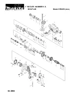
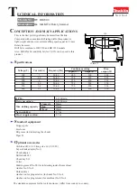
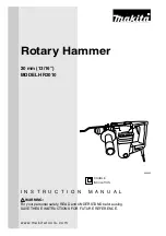
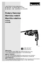
 

PRODUCT NAME 

Cordless Rotary Hammer 

Models


18 V


DH 18DPA 

10.8 V


DH 12DD 

DH 18DPA 

DH 12DD 

Та

ше

в

-

Га

лв

ин

г


ОО

Д


www.tashev-galving.com

Summary of Contents for DH 12DD

Page 1: ... 12 Lubrication points and types of lubricant 13 Wiring diagram 16 2 Precautions on disassembly and reassembly of the charger 17 CONTENTS Page D CONFIDENTIAL Jan 2021 Overseas Sales Management Dept PRODUCT NAME Cordless Rotary Hammer Models 18 V DH 18DPA 10 8 V DH 12DD DH 18DPA DH 12DD Т а ш е в Г а л в и н г О О Д w w w t a s h e v g a l v i n g c o m ...

Page 2: ...l DH 18DPA and Bold numbers to those for the Model DH 12DD 1 Disassembly of the tool retainer ass y Fully pull the Grip 4 4 in the arrow direction and remove the Front Cap 2 2 Remove the Stopper Ring 3 3 with a retaining ring puller while pulling the Grip 4 4 in the arrow direction Remove the Grip 4 4 Ball Holder 5 5 Steel Ball D7 0 19 19 Holder Plate 6 6 and Holder Spring 7 7 from the Cylinder 20...

Page 3: ...49 49 NOTE The Seal Lock Hex Socket Hd Bolt M5 x 14 34 34 loses its bonding force if removed Use the new Seal Lock Hex Socket Hd Bolt M5 x 14 34 34 at reassembly 3 Disassembly of second shaft A ass y Engage the claw of the Clutch 44 44 with the claw of the Reciprocating Bearing 45 45 and place the Clutch 44 44 on a cradle as shown in Fig 3 Push the rear end of Second Shaft A 43 43 with a hand pres...

Page 4: ...1 punch C into the two 4 mm dia hole 2 places on the Cylinder 20 20 and hammer the punch head to give force to the periphery of the Stopper Ring 25 25 in order to detach the Stopper Ring 25 25 from the bore groove of the Cylinder 20 20 At this time fully hammer along the periphery of the Stopper Ring 25 25 until the Stopper Ring 25 25 disappears from the two 4 mm dia holes Then unclamp the Cylinde...

Page 5: ...NOTE The Stopper Ring 25 25 has a white mark to differentiate from the Stopper Ring 3 3 Push the new Stopper Ring 25 25 into the Cylinder 20 20 with the break of the Stopper Ring 25 25 facing away from the 4 mm dia hole on the Cylinder 20 20 as shown in Fig 5 If the ring break is faced toward the 4 mm dia hole it may be hard to disassemble the cylinder ass y 3 Use a hand press to press against the...

Page 6: ...3 13 into the groove inside the Change Lever 11 11 Then push the Change Lever 11 11 in the hole of the Gear Cover 9 9 as far as it will go NOTE Push the Change Lever 11 11 in the Gear Cover 9 9 without tilting so that the O ring 12 12 is not twisted 3 Set the Change Lever 11 11 to the Rotation Hammering mark position Tighten the Machine Screw M4 x 5 14 14 to fix the Change Lever 11 11 to the Gear ...

Page 7: ...nd of the J 408 bevel gear jig Then remove the J 408 bevel gear jig and mount it in reverse direction as shown in Fig 8 and push Second Shaft A 43 43 with a hand press until the end of Second Shaft A 43 43 contacts the end of the J 408 bevel gear jig NOTE After reassembly of the second shaft ass y check the following Check that the Reciprocating Bearing 45 45 rotates around Second Shaft A 43 43 sm...

Page 8: ...er A Ass y 49 49 3 Insert the arm of the Reciprocating Bearing 45 45 of the second shaft ass y into the Piston 31 31 so that the arm of the Reciprocating Bearing 45 45 is sandwiched between the two Washers 42 42 as shown in Fig 9 Insert the rear end of Second Shaft A 43 43 into Inner Cover A Ass y 49 49 4 Allow the inner ring of the Reciprocating Bearing 45 45 to make one rotation and check that t...

Page 9: ...3 mm dia shaft of the Change Lever 11 11 and Machine Screw M4 x 5 14 14 3 Set the Change Lever 11 11 on the Gear Cover 9 9 to the Rotation Hammering mark position Press the Gear Cover 9 9 against Housing A B Set 63 63 so that they are properly mounted At this time check that the Piston 31 31 is inserted into the Cylinder 20 20 NOTE Be careful not to get O ring A 36 36 caught between the Gear Cover...

Page 10: ...rwise it may cause a malfunction or accident 3 Put the panel ass y in housing A so that the internal wires between the panel ass y and the main PCB ass y are positioned as shown in Fig 13 NOTE Align the internal wires between the panel ass y and the main PCB ass y horizontally to prevent disconnection 61 61 Connector Connector cable Insert the connector cable securely until it is locked Battery te...

Page 11: ...en put the cable sleeve sheathed internal wire between the main PCB ass y and battery terminal in housing A Fig 14 Stator FET PCB ass y LED Main PCB ass y Stator FET PCB ass y Battery terminal Red and black internal wires Main PCB ass y Cable sleeve Stator FET PCB ass y Cable sleeve Model DH 18DPA Model DH 12DD Battery terminal Red and black internal wires Main PCB ass y Т а ш е в Г а л в и н г О ...

Page 12: ...roduct by following the procedure below 1 After reassembly check that the Change Lever 11 11 is switchable between the Rotation Hammering mark position and Rotation only mark position 2 Set the Change Lever 11 11 to the Rotation Hammering mark position Insert the SDS plus shank into the Cylinder 20 20 Let the Cylinder 20 20 make one rotation and check that the fan rotates 3 Set the Change Lever 11...

Page 13: ...ndle and the side handle securely pull the switch to check that the slip clutch operates 4 Check that the Change Lever 11 11 turns smoothly and the operating mode properly switches between Rotation only mark and Rotation Hammering mark according to the operation of the Change Lever 11 11 Tapping Screw W Flange D4 x 30 Black 8 8 2 0 0 5 N m 20 5 kgf cm Machine Screw M4 x 5 14 14 0 8 0 2 N m 8 2 kgf...

Page 14: ...r surfaces of the Needle Cage 46 46 Thrust Washer C 47 47 Reciprocating Bearing 45 45 rotating shaft and spline of Second Shaft A 43 43 Fig 22 Tooth plane of the Bevel Gear 48 48 Fig 23 1 5 g Tooth plane of the rotor ass y pinion of Inner Cover A Ass y 49 49 Fig 26 Inner circumference of the needle bearing of Inner Cover B 35 35 Outer surfaces of the Piston 31 31 inner and outer surfaces of the Pi...

Page 15: ...he ball portion Apply to the arm Apply to the bore surface Apply to the rotating shaft of the Reciprocating Bearing 45 45 Apply to the spline Apply 1 5 grams of grease to the tooth plane of the Bevel Gear 48 48 Apply to the outer surface Apply to both sides Apply to the inner surface Apply to the outer surface 22 22 18 18 20 20 21 21 45 45 20 20 43 43 31 31 42 42 41 41 29 29 30 30 Т а ш е в Г а л ...

Page 16: ...t 6 grams of grease in the rear of the piston 49 49 Apply grease to the tooth plane of the rotor ass y pinion Put 15 grams of grease in the Gear Cover 9 9 Т а ш е в Г а л в и н г О О Д w w w t a s h e v g a l v i n g c o m ...

Page 17: ...ng diagram Fig 28 Wiring diagram of the Model DH 18DPA Fig 29 Wiring diagram of the Model DH 12DD 61 61 Panel ass y Panel ass y LED LED 64 65 Т а ш е в Г а л в и н г О О Д w w w t a s h e v g a l v i n g c o m ...

Page 18: ...o the service manuals for precautions on disassembly and reassembly of the charger Models UC 18YFSL and UC 12SL LED light Controller ass y 6 pin connector cable F 18 pin ribbon cable ass y FET PCB ass y Panel ass y Battery terminal ass y Т а ш е в Г а л в и н г О О Д w w w t a s h e v g a l v i n g c o m ...

Page 19: ... 14 13 15 16 17 18 19 20 21 22 23 24 25 26 27 28 29 30 31 32 33 34 35 36 47 37 41 42 43 44 45 46 48 38 60 39 40 63 65 62 66 64 64 501 504 503 505 502 506 507 509 510 508 61 49 58 59 1 50 Т а ш е в Г а л в и н г О О Д w w w t a s h e v g a l v i n g c o m ...

Page 20: ...1 38 376328 HANDLE PLATE A 4 39 376329 HANDLE PLATE B 4 40 301653 TAPPING SCREW W FLANGE D4 X 20 BLACK 11 41 306322 PISTON PIN 1 42 328660 WASHER 2 43 376322 SECOND SHAFT A 1 44 376593 CLUTCH 1 45 325585 RECIPROCATING BEARING 1 46 306320 NEEDLE CAGE 1 47 376675 THRUST WASHER C 1 48 376324 BEVEL GEAR 1 49 377012 INNER COVER ASS Y A 1 INCLUD 37 50 58 59 50 626VVM BALL BEARING 626VVC2PS2L 1 58 376332...

Page 21: ...ENCH FOR 13VLB D 13VLR D 1 609 971787 DUST CUP 1 610 372200 HOOK 1 611 337357 TRUSS HD SCREW M4 BLACK 1 612 335782 GREASE FOR ROTARY HAMMER 60 G 1 613 335781 GREASE FOR ROTARY HAMMER 500 G 1 614 376690 GREASE FOR CORDLESS ROTARY HAMMER 50 G 1 615 306885 DUST COLLECTOR B ASS Y 1 INCLUD 616 616 306910 SOCKET ADAPTER B 1 617 321813 DRILL CHUCK 13VLD D 1 INCLUD 602 618 971511Z DRIVER BIT A NO 2 25L 1 ...

Page 22: ...6 507 509 510 508 8 9 10 11 12 14 13 15 16 17 18 19 20 21 22 23 24 25 26 27 28 29 30 31 32 33 41 42 43 44 45 46 65 2 3 4 5 6 7 34 35 36 47 37 48 1 38 60 39 40 63 64 62 61 49 58 59 50 Т а ш е в Г а л в и н г О О Д w w w t a s h e v g a l v i n g c o m ...

Page 23: ...LT PACKING A 1 38 376328 HANDLE PLATE A 4 39 376329 HANDLE PLATE B 4 40 301653 TAPPING SCREW W FLANGE D4 X 20 BLACK 11 41 306322 PISTON PIN 1 42 328660 WASHER 2 43 376322 SECOND SHAFT A 1 44 376593 CLUTCH 1 45 325585 RECIPROCATING BEARING 1 46 306320 NEEDLE CAGE 1 47 376675 THRUST WASHER C 1 48 376324 BEVEL GEAR 1 49 377012 INNER COVER ASS Y A 1 INCLUD 37 50 58 59 50 626VVM BALL BEARING 626VVC2PS2...

Page 24: ...B D 13VLR D 1 609 971787 DUST CUP 1 610 372200 HOOK 1 611 337357 TRUSS HD SCREW M4 BLACK 1 612 335782 GREASE FOR ROTARY HAMMER 60 G 1 613 335781 GREASE FOR ROTARY HAMMER 500 G 1 614 376690 GREASE FOR CORDLESS ROTARY HAMMER 50 G 1 615 306885 DUST COLLECTOR B ASS Y 1 INCLUD 616 616 306910 SOCKET ADAPTER B 1 617 321813 DRILL CHUCK 13VLD D 1 INCLUD 602 618 971511Z DRIVER BIT A NO 2 25L 1 619 971512Z D...

Reviews: