background image

Summary of Contents for D-900

Page 1: ...eferung eines reparierten Geràtes an den kunden muR der Wartungstechniker das Geràt einer grùnd lichen Prúfung unterziehen um sicherzustellen daB sicherer Betrieb ohne die Gefahr von elektrischen Schlàgen gewàhrleistet ist Précautions de sécu rité Les précautions suívantes doivent étre observées à chaque qu une réparation doit étre faite 1 Etant donné que de nombreux composants de I appareil possè...

Page 2: ...fnahmepegelregler 16 Aufnahmepegelregler 17 Dolby NR chalter UKw tereo Hóhenf ilter 18 Entzerrungs Bandsortenwàhler 1 I Vormagnetisíerungs Bandsortenwàhler 20 Monitorschalter 21 Auswerftaste 22 Redigiertaste 23 Pausentaste 24 Sîopptaste 25 Schnellvorlauftaste 26 Starttaste 27 Rúcklauftaste 28 Aufnahmetaste 29 Netzschalter 30 Kopfhórerbuchse 31 Mikrofonubuchse rechter Kanal 32 Mikrofonbuchse linker...

Page 3: ... x 43 5 Wl x 25 4 Dlcm 8 5 ks DC Servo motor R Pcombinationheadxl Erase head x 1 Technische Daten Bestúckung lCs Transistoren Dioden Zenerdioden Spursyfem Tonband Bandgeschwindigkeit Aufnahmesystem und Vormagnetisierungsf requenz Lòschsystem L6schdàmpfung Frequenzgang Normalband CrO2 Band FeCr Band F remdspannungsabstand ohne Dolby mit Dolby G leichlauf schwankungen E ingangsempf indlichkeit und l...

Page 4: ...5 kHz 30 Hz à 20 kHz 25Hzà 18 kHz 20 Hz à 18 kHz 25Hzà15kHz 55 dB 56 dB 63 dB 63 dB 0 057 wRMS o 15 o 0 3mV 30O ohms SK ohms C AU 0 25mV 300 ohms 5K ohms W BS FS 60mV 10OK ohms ou plus 0 3mV 3 3K ohms C AU 1mV lOK ohms W BS FS 500mV ou plus SOK ohms ou plus SOK ohms ou plus C AU 470K ohms W BS FS 8 ohms à 2K ohms 1 5 ll kHz 0VUÌ 60 dB à 1 kHzI ou plus 30dB à 1 kHzl ou plus 1 20 secondes avec une c...

Page 5: ... and in the figure of ltem 4 12 Control PC Board 13 Main PC Board Demontage 1 Cassettenfachdeckel 2 Knópfe Die Knòpfe der Hebelschalter l tisierung Entzerrung Dolby NR u Kalibrierung links rechts Ausgangsl der Frontplatte einfach abgezogen w Die Tasten Speicher Bandzàhlwerk werden von der Rùckseite abgen entfernt wurde 3 Obere Abdeckung 4 Bodenplatte 5 Frontplatte Die Frontplatte abnehmen nachdem ...

Page 6: ...és par le panneau avant Les interrupteurs et boutons MEMORY COUNTER METER DCCS TEST sont retirés par l arrière après dépose de la fagade 3 Plaque supérieure 4 Plaque inférieure 5 Fagade Déposer la plaque de fagade après dépose des clefs de commutation des boutons de réglages et interrupteurs et du volet de cassette 6 Ensemble des touches de commande 7 Plaquette à circuits imprimés de témoin de 3 t...

Page 7: ...tor TAPE S5 lnstrument VU S6 Dolby Kalibrierung OFF S8 Netzschalter ON s20 Speicher OFF RV1 Aufnahmepegel Max RV2 Aufnahmepegel Max RV3 Dolby Kalibrierungs Aufnahmepegel Mittel stellung RV4 Ausgangspegel Max Anordnung d D 9 0 REGLAGES Procéder aux réglages suivants et dans l ordre spécifié après avoir nettoyé la surface des tétes magnétiques du galet presseur et le cabestan avec un bàtonnet de net...

Page 8: ... guide de bande et l orientation de la téte combinée enregistrement lecture avec les vis b et c Ensuite utiliser une bande de con tróle MTT 114 lOkHz Pour ajuster l azimuth de la téte combi née enregistrement lecture en utilisant la vis a pour obtenir un niveau de sortie maximum î t c I frJlTT 111 3000H2 3150H2 l Adiustment Warm up the unit for approximately 20 minutes then playback test tape MTT ...

Page 9: ...r auf Position PEAK stellen und RTB L R einstellen so daB die Anzeigenadeln der lnstrumente bis zur Dolby Markierung DC ausschlagen 3 Den lnstrumentenschalter da nach auf Position VU stellen und RT7 L R einstellen so da8 die Anzeigenadeln der lnstrumente bis zur Dolby Markierung l 1 ausschlagen 4 Danach den Monitorschalter auf Position TAPE stellen Ein Prúf band MTT 150 400 Hz 2Om Maxwell abspiele...

Page 10: ...ntrol or the signal generator for an output of O 775Y at Pin Nos 8 L 9 R of lC2 Next set the Monitor switch to SOURCE and adjust RT2 L R for an output of O 775Y at Pin Nos 8 L 9 R of lC5 Abgleich Ein 400 Hz Signal an den LINE lN Buchsen einspeisen Den Aufnahmepegelregler oder den Si gnalgenerator einstellen bis eine Ausgangsspannung von O 775V an den Stiften Nr 8 L und 9 R von lC2 anliegt Danach d...

Page 11: ...osition TAPE Appliquer des signaux de 1 2kHz et de l2kHz aux prises d entrée de ligne LINE lN avec un réglage de niveau de 20VU Ajuster RT9 L R pour que la différence de niveau de sortie soit de OdB 1dB b Régler la clef de contròle sur la position SOURCE et appliquer un signal de 400H2 aux prises d entrée de ligne LINE lN pour que les VU mètres indiquent 0VU En suite régler la clef de con tróle su...

Page 12: ...e contróle sur la posi tion TAPE et s assurer que les VU mètres signalent un niveau de sortie de 0VU Réduire le niveau d entrée de 20dB enregistrer des signaux de 1 5kHz et l5kHz et lire le résultat pour étre certain que le niveau de sortie à la lecture est de OdB ldB Si le résultat ne correspond pas à ces spéci fications réajuster RT9 L R Répéter les réglages si une différence apparaft entre les ...

Page 13: ... von lCS 15 7 dBm betràgt Danach den Dolby NR Schalter auf Position ON stellen und RTG L R einstellen bis der Pegel an den Stiften Nr 8 L und 9 R von lCS 20dBm betrart Róglage Appliquer un signal de 2kHz aux prises d entrée de ligne LINE lN pour que le niveau de sortie aux broches Nos 8 L 9 R de lC2 soit égal à 20dBm En suite basculer la clef de com mutation de Dolby sur ON Ajus ter RTî L R pour q...

Page 14: ...ller Supply side Torque Take up 35 to 609 m Fast foruard 75 to 1 209 cm Rewind 75 to 1 209 cm Drehmomente Aufwickelteller 35 bis 60 g cm Schnellvorlauf 75 bis 120 g cm Riicklauf 75 bis 120 9 cm Couple En roulement 35 à 60gr cm Avance rapide 75 à 12Ogr cm Rembobinage 75 à 1 2Ogr cm Back tension Take up reel Less than Sgrm Note Measure it in the rewind mode Supply reel 8 to 129 cm Note Measure it in...

Page 15: ...es d utilisation Eviter de trop mettre d huile car la rotation peut devenir irrégulière à la suite d éclaboussures d hu i le A A A During mode switching Less than 1 sec for STOP Note There is a STOP interval of less than 1 sec when switch ing from each mode Eject From 0 5 îo 3 O sec Note Time required for the cassette lid to open completely after the EJECT button is de pressed Wàhrend des Umschalt...

Page 16: ...Ax OUTPUT RV4l MAX DCCS RECOFD RV3l adjusted Switches MONITOR S4 TAPE BIAS S3l NOR EOUALI ZER S2 NOR DOLBY S1 l OFF MPX Sl OFF 0dB O 775V lnput 4OOHz LINE lN 2OdB MIC 68d8 DIN 68d8 Controlsi RECORD LEVEL RVi MAX RECORD LEVEL RV2l MAX OUTPUT RV4 MAX DCCS RECORD RV3l adiusted Switches MONITOR S4l SOURCE BIAS S3l NOR EOUAL IZER S2 NOR DOLBY S1l OFF MPX Sll OFF 9 6adB 6adB 16 ...

Page 17: ...DbL R IC 6 q2 L e ri6oP ifr as 23Ct 4 IEf FOR EÎE OC AXP FoR TETEi 6 AY DOI BÍ 3V D3L R Dza C3r CA R tiga rgTtc 2scr7 s 2scre REcîFoFm rr __ _gEg l EL o L 1 E2a t l t gf Fil t ozc r s2aÉl a3t I drqr xe 9 tSrRch r rr l L_ Y___ i 0a8L R tsXErc R CT e 2rc4 L G olim PLAY ATE CNqII uYmf Eo r I L tc 7 L R u 16 HÉAD ATP gsffi D15 O15 vo ffi o11 x2 t5 vcî a CI L R 25C46 gC RJIY SIOi L nmio craL R 2SCr740 ...

Page 18: ...Ft l Cl6 ef 2Strc r EroPrfrG aF tr s AU o2q oito fe63 aaff HHFfr i r s tr4ry gEeq iffiee filn e RÉrcfE TÎML Jld w Y reru xt v drE WG r ot6 Dt5 m7 3 vo e rs24 3rc MF NSFR ot7 HZ t5 vcî sr ar A o20 2SCtrc Edfflr frîB gfF o32 IN34A 9 RÉAEI crREtf occl OPERANNG arTToîts t l 18 Y ...

Page 19: ...akte rs k hlben Lorsqua lrg condaas taur poilant lè raFarc utrh r caur qur nt prócrtas dan3 la h3ts da prècar dótacha 3 ótant donnó bur cr acîóiatqu i da tamÉratura CIRCUIT BOARD DIAGRAM AMP SECTIONI s s I I I I lr 4 i 3 tso l1 l 1 tl L lr tt tl r I L____ I I I I I I I I I I I Ctrcurl No Schahk ara Nr No de crrcuI Wrda6tand No rndrcatad K n Bererchnuno U Ohhl No rndrqué M toooHt folafanc lolaranl ...

Page 20: ...floNt ORN RE î f c6F _ 6 RI L I o qoo tNE C AU ItaE DrN W 85 FS l csFù tc2 Num rols in Q ore connocted wl h îho o of 20 ...

Page 21: ...OP PAUSE MODE t lol_o PLAY SIGNAL GENERATION lc7 H07400P PLAY I ODE HOLD rJttEot INVERTER D69 D7t tN60 BOOSTING DISCHARGE REMOTE NTROL JACK OPERATING BUTTONS r l PLAY STOP REC 053 D80 rN 60 RFÚERSE CI IRRENT CHECK s6 R54 470 tc4 D rc 055 rN60 BOOSTING DISO ARGE rîT l ùlmry nl r rwltch lurm ON wlth 999 D8r tN60 REVERSE CURRENT CHECK Auft ff o57 zSCt740 PAITSE RESET SIGNAL GENERATION 2 1 t L __ D83 ...

Page 22: ...u mlor wllh FG TO AMP CRqJT v Yt v V l J OPERATING zuTTOî I INDICATOR 067 068 2SCt740 2SCtO6t sv sv SWITCHING OLT STABI F D6r O59 HZ6A WO6A i t R ttt s tABt 060 r06A 5v RECT FOR SWTCHING orc 07 2SC D6r HTftF f r_23lYl ctrt to 063 wo6A HIGH VOLTAGE REVERSE CURRENT CHECK o6cr 07233 064 D66 06 E fiiffir f ffi Ftr ffi lC I 3 Itu d 3 hpu commm 4 or lnv îtcr by 3lgnol Itr Til lor ns lo I I rs used os ln...

Page 23: ... CIRCUIT BOARD DIAGRAM CONTROL SECTION 38 5 R54 5t j 72 I ICil 22 og 3 _jili_ 5 6 d6C hsr6 AAr R v c507 nÉse Ìff CONTROL AAA R528 osrì il R5t7 R524 lCZ 5 _23 ...

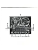
Page 24: ...INDICATOR p I Ttrts dlogrom indicoÎes 24 ...

Page 25: ...CIRCUIT BOARD DIAGRAM RV3L R DCCS RECORD s6 TEST S5 METER O ore connectod to moin PC Boord e ...

Page 26: ...Y Yr Mtc HEADPHONE J5 Ur Y v ...

Page 27: ...WIRING DIAGRAM s f E l À ft Pdr lrúaf ú s pluPb p lffib 6 Fa dh s qTROL P C A Pod tù w mdll L l Yl vu da f1 R u t ...

Page 28: ... I Li ff i tl 3 J ÙJq X 3 28 ...

Page 29: ...D 9 0 D 9 EXPLODED VIEW 6 U 2 Sr6 I l î a L rìx h 6 25 28 4XtO 29 ...

Page 30: ...ts marked without numbers in this drawing are not specified as replacemont parts Die ohne Nummer in dieser Zeichnung angegebenen Teile sind keine spezifizierten Ersatzteile Les pièces sans numéros indiquées sur le schóma no correspondent pas a des pieces de rechangc 6 30 u ...

Page 31: ...EXPLODED VIEW I I J qt 31 ...

Page 32: ...I o roo 32 ...

Page 33: ...R i LR D4 I 8LR t 9LR DI LR DI I 1 12 0ll Dl4 015 D1ó 017 016 Dt9 020 D2l D22 o2t D24 tr25 D26 D27 D2IIL R 029 010 Dll 0t2 o52 Dsl D54 055 05ó 58 059 0ó0 0ó1 Dó nó4 L ó5 Dó6 Dó7 Dó8 7 t 080 n8 082 081 084 rcl tc2 tc3 tc4 tc5 rc6 tc7 tc8 tc9 tc10 tc11 ICl LR tc2 5180101 RAolAfl0N 0100E SLP 241i 5tt0512 0loDE StLtcoN ls247rHc l00MHl 250HrJ l0Ns 51t0572 Dl00E stLtcoN l5247lt1c t00ilHz 250íH I0Ns 5330...

Page 34: ... 532rî92 Tr ANSI5l0R 25C1740s 2N6 tt îRAfrslsloR slLfcoN 2scl0óltl rt Hz 50w 5t2L292 tRANSl5l0R 2SC17405 1 120ó71 ft Al slsl0R SlLlCoN 2SCl0ólB SHlrz 50 v l 5r20ó7t fRANSlsloRSlLlc0N 2sc10ó10 5MHZ 50 5120è21 fRANSlsToR StLICoN 25Cl2lJA C 80llHZ 400Mr 5a2O62t rRANSlST0rì SILICON 25 I2l lA C 60llHZ 400Mt 1 5321292 fR N5lsf0R 2SC1740S 0óI 0ó2 ó3 ó5 ó7 ó8 ó9 7o c 0 0 7t o 72 0 7t 074 07nlLR 5t20ótl TR...

Page 35: ...s f 48 49 50 5l 52 5t 54 55 5ó 57 98 59 ó0 ó1 6 ó3 ó4 ó5 óó 67 ó8 ó9 70 7l 72 67 4155L 72A7 096 ó12r991 1287 Lt5 766L777 7L07057 óll9ó9t 6t25061 7290501 ó 74 4101 ó5602t4 órr970l 729557t 729t551 6t25296 7290491 7 A7462 7574Èt2 7t07ltt 5642trl 642t41 5642ttl 54445t1 54451ót 56t2052 IHRUSI SUPPOIif FASI FOR ARD SL I DER 5PR I N6 REI I I ND SL I DER SPRING SUPPORT CASSEfÎE HOLOER ASSEIBLY SPR I NG sp...

Page 36: ...l 3llLoxl2XX 8LACK 8747ó08 EINO SCREr 4Flox8Hr l BLACK 77867t1 SPECIAL hlASfrER 88r5tr4 LoCK HASIIER rllllD 109 104 105 106 107 a I I I I I I I I I I I I I I î l llitt Ll rl i lii lolùiol li tl tr rl ll tt tt tt tt ll Ir I I I I I I L_ __ Typo of h 6d Sch16ubana a Typo d tat P Zylnderschraube Vis A téte tronconrqu B BT Sinding head rapprng screw Halbrúnd Selbstschnerd schraube mtr flachem Kopf Vis...

Page 37: ...9 L NE AMP J2R lMrc Rtl J4 lorNl 23Ct740 DCCS OSC tc8 HAt452 LINE AMP Q6L R 2SCt740 DOLBY NR SWITCHING r c 7L R HAt406 HEAD AMP RTIOL R SIGNAL QI7L R 25D467BC tvlurlNG eTsp earr E1 c B s2 st TI DI5 POWER wo6A TRANSFORMER pOWER REc Dt6 wo6A POWER RECT I ar8L R 2SCt740 PLAY EO N o Ql2L R 2SCt740 DOLBY NR SWITCHING Q26 2SCIO6t Dt7 HZ S T STAB e AC POWE SOURCE AC POWER CASSETTE D27 B D27 wo6A POWER RE...

Page 38: ...rs2473t C REVERSE CURRENT CHECK J6 DtN MONTTOR BS FS W Qt6 2SD468B J3LR Q74 25Ct740 ITINE ourl BrAs swtrcHrNc 3SEC POWER 4 DI I S 2473HC COUNTER ELECTROi lOTIVE FORCE CHECK J5 OFF Q29L R 23Ct740 MUTING Dt4 ts2473HC REVERSE CURRENT eec Ec pt lv srerlt Q5 2SCt740 DIN OUTPUT SWITCHING QI3L R 2SCt740 HEADP oNE AMP cHEcK 3r1i f P ilT RECT FOR METER 5v tc6 NJM 4558 METER AMP RV3L R D23 24 SW TCH NG Dz4 ...

Page 39: ... EJECT PAUSE st6 sl7 REC 056 tc5 tc7 To FFlREW solenoid FF REW STOP PULSE SIGNAL D65 tc2 Q73 69 Q70 iAARK INDICATES LOGICAL VALUE coNvERsoN crRcurî GENE RAIES FF FLIP _ FLOP F F GATE GATE FOR FF RESET REW PULSE G ENERAT ES GATE FOR REW RESET PLAY PULSE GENERATES GATE AMP GATE FOR REW RESET f l i n sn PLAY REC SIGNAL GENERAT ES REC GATE S IGNAL GENERATES HIGE LOW VOLTAGE SELECTOR 063 39 ...

Page 40: ...LES NORWAY A S Nygaardsgt 49 51 N 1600 Fredrikstad Norway Tel Fredrikstad 11 14O SUOMEN HITACHI OY Box 151 SF l510O Lahti 1O Finland Tel Lahti 44 241 HITACHI SALES A S Kuldyssen 13 DK 2630 Taastrup Denma rk Tel O2 9992OO HITACHI SATES A G 5600 Lenzburg Switzerland Tel 064 513621 HITACHI FRANCE Radio Télévision Electio Ménàger S A 9 Boulevard Ney 75018 Paris France fel 2O1 25 0O HITACHI SATES AUSTR...

Reviews: