background image


INSTRUCTION MANUAL


HITACHI 
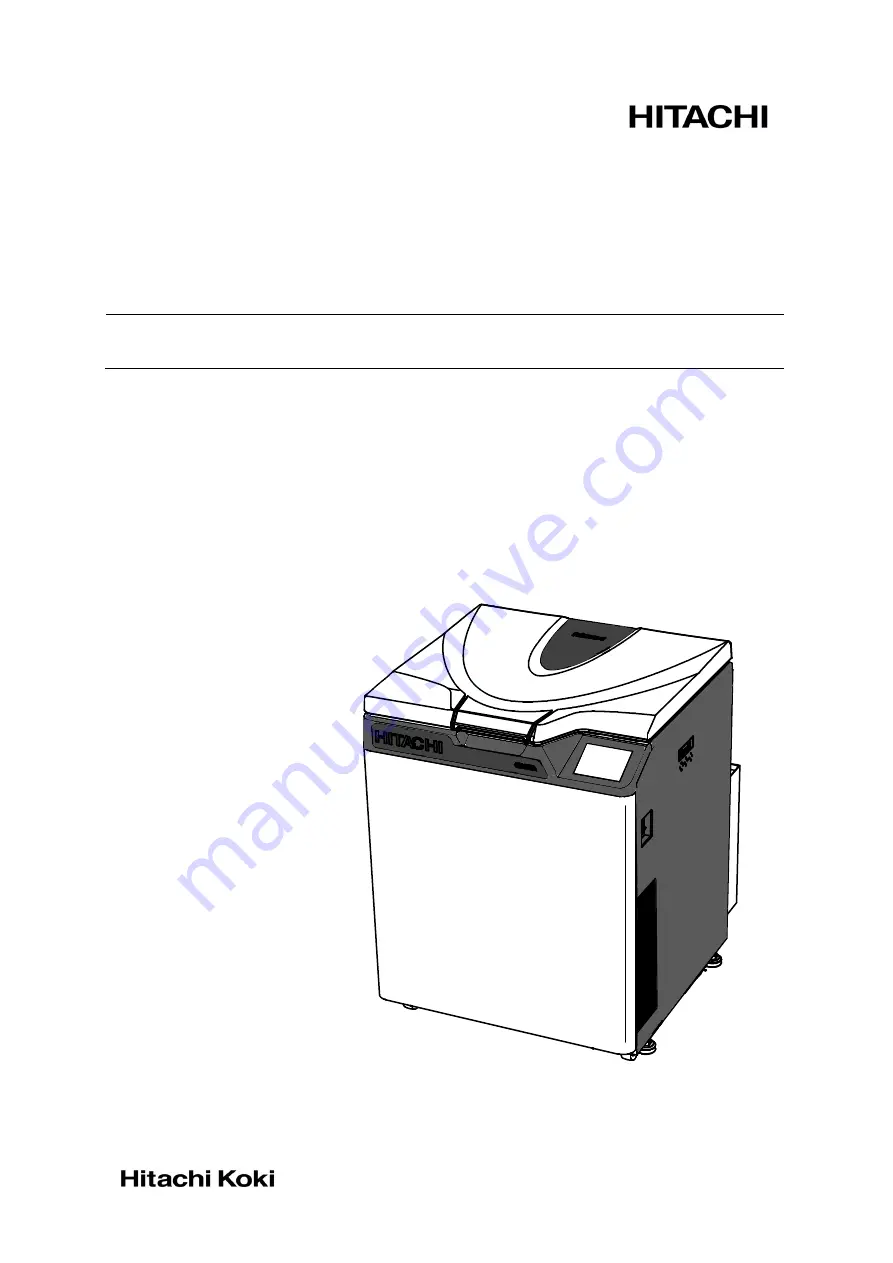
HIGH-SPEED REFRIGERATED CENTRIFUGES 

CR22N/CR21N

Thank you for purchasing the Hitachi 
high-speed refrigerated centrifuge. 
Before using this centrifuge, 
carefully read through 
this instruction manual to ensure 
efficient and safe operation. 
Keep this instruction manual handy.


2015.10 
S99840305 

The appearance or specification of the products covered in this manual is 

subject to partial change for improvement.


Summary of Contents for CR21N

Page 1: ...gh speed refrigerated centrifuge Before using this centrifuge carefully read through this instruction manual to ensure efficient and safe operation Keep this instruction manual handy 2015 10 S99840305 The appearance or specification of the products covered in this manual is subject to partial change for improvement ...

Page 2: ......

Page 3: ...s reserved No part of this document may be reproduced or transmitted in any form or any means without permission from Hitachi Koki Co Ltd The names of actual companies and products mentioned herein may be the trademarks of their respective owners ...

Page 4: ...perform any operation not specified in the instruction manual If any problem is found on your instrument contact a Hitachi Koki authorized sales service representative Although the safety precautions in the instruction manual and safety instructions on your instrument have been fully considered an unexpected situation may arise Observe the instructions in the instruction manual and always be caref...

Page 5: ...ed to the rotor and do not use any sample inapplicable to the tubes the bottles the tuberacks the microplates or tube bottle caps etc Using such a sample could deteriorate such parts Maximum rotor speed depends on the buckets assemblies tubes or adapters to be used Follow the instructions on the rotor instruction manual Do not exceed the allowable imbalance Use the rotor tubes and bottles within t...

Page 6: ... the door the cover of the left side of the centrifuge and the caps of the inside of rotor chamber if your centrifuge is the CR21N refrigerated centrifuge A continuous flow rotor is not applicable to the CR21N refrigerated centrifuge Installation or relocation of your centrifuge must be done by the authorized Hitachi Koki service representative Contact a Hitachi Koki authorized sales service repre...

Page 7: ... to good laboratory procedures and methods If there is a possibility that the centrifuge rotor or an accessory is contaminated by samples that might impair human health for example samples that are toxic or radioactive or blood samples that are pathogenic or infectious it is your responsibility to sterilize or decontaminate the centrifuge rotor or the accessory properly before requesting repairs f...

Page 8: ...he FUNCTION Area 2 15 2 3 1 Programmed Operation 2 16 2 3 2 Step Mode Operation 2 30 2 3 3 Displaying and Setting RCF 2 32 2 3 4 Displaying and Setting g sec 2 37 2 3 5 RTC real time control Operation 2 40 2 4 Selecting the Rotor 2 44 2 5 User Login 2 46 2 6 Features of the MENU Screen 2 48 2 6 1 Displaying the Run History and Loading the Information About Run Parameters 2 49 2 6 2 Rotor Catalog 2...

Page 9: ...llation and Relocation 5 1 6 Warranty 6 1 6 1 Warranty on Centrifuge 6 1 6 2 Warranty on Rotor 6 1 7 Specifications 7 1 8 List of Standard Accessories 8 1 9 Tubes and Bottles 9 1 APPENDIX Decontamination sheet WEEE Compliance Marking for Control of Pollution Caused by Electronic Information Products THE PEOPLE S REPUBLIC OF CHINA ...

Page 10: ...MEMO ...

Page 11: ...rnal View of Centrifuge POWER switch 1 Structure 1 1 External View of Centrifuge Touchscreen display operation 760 mm 29 9 in 700 mm 27 6 in 853 mm 33 6 in Front cover Ultrasonic sensor Table Door Gas spring Rotor chamber Drive shaft crown Drain hole Rotor ID sensor Temperature sensor Evaporator Seal rubber Over speed sensor 700 853 760 1 1 ...

Page 12: ...User Customizations Screens by pressing the screen Fig 1 2 1 shows the touchscreen The following screen appears by pressing the SPEED TIME or TEMP area 7 RTC button 4 PROGRAM button 3 STOP button 2 START button 1 2 Structure 1 2 1 Touchscreen Fig 1 2 1 Touchscreen Display at the normal operation 1 Display areas Tabs of each screen 8 USER button Display when setting the run conditions such as the s...

Page 13: ...ng operation time If the running time is set to HOLD the upper part displays the elapsed time Lower part Used to set and displays a range from 1 second to 99 minutes 59 seconds in increment of seconds and minutes Option Used to set and displays a range from 1 minute from 99 hours 59 minutes in increment of minutes and hours TEMP Temperature indicator Upper part Displays the temperature in incremen...

Page 14: ...ng a temperature If a temperature is below zero press this to enter minus sign Hold When entering the operation time Sets continuous running CE Press this to cancel input for example if you enter the wrong number or the wrong value for a run parameter Enter Press this to save the entered setting x Press this to close the on screen keypad No Name and symbol Functions and actions 4 button Press this...

Page 15: ... The door can be opened closed only when the rotor stops 4 Dual overspeed detector This centrifuge is equipped with a sensor that does not allow the rotor to rotate over the allowable maximum speed 1 If improper speed over the allowable maximum speed is set the overspeed detector detects it when the rotor is running at low speed 300 rpm and displays an alarm message SPEED 2 Even if the improper op...

Page 16: ...fugal Force The centrifuge automatically computes RCF values from set speed or speed from set RCF values and then displays the result of computation on the control panel Section 2 3 3 Displaying and Setting RCF Displaying and setting g sec This centrifuge automatically computes and displays integrator g sec values from RCF and run time The centrifuge can also be operated by entering integrator g s...

Page 17: ...amples at your own responsibility CAUTION Do not place containers holding liquid in the rotor chamber on the centrifuge or near the centrifuge If spilt liquid might get into the instrument and damage electrical and mechanical components 2 1 1 Starting up This Machine Before setting run conditions display the Run screen Screen for setting run conditions 1 Displaying the Run screen Screen for settin...

Page 18: ... the following cases Fill the same sample in the same tubes bottles and load them in the buckets that are placed symmetrically with respect to the drive shaft in the rotor If samples that are equal in volume but different in composition are used the precipitation levels may be different by centrifugation and such operation may increase the level of imbalance If samples that are equal in weight but...

Page 19: ...g Run Conditions This section will first describe the screen for basic operation the Run screen For the display at the normal operation and the display when setting the run conditions refer to Section 1 2 1 Run screen The screen for displaying the specified setting and current status is called the Run screen The SPEED TIME and TEMP areas display the current status in the upper part and the specifi...

Page 20: ...or of the upper part Blue 2 Enter the desired numeric value with the on screen keypad e g SPEED 22 000rpm Press the 3 If you do not want to change any other setting press the button on the on screen keypad If you want to change other settings press the area of the desired item and the pressed area will become the input wait state The new setting is displayed In the lower part of the pressed area O...

Page 21: ...SPEED TIME and TEMP you do not have to press the Enter button after each setting You can store the setting by pressing the desired item 3 If the system is running in HOLD and you want to set it to shut down at a future time enter a new time setting while the instrument is in operation enter the sum of the time elapsed plus the time remaining If for example this machine has run continuously for fiv...

Page 22: ...the button Use the button to cancel input Set it to 22 000rpm Set it to 2 30 2 minutes 30 seconds Set it to 4 C Setting range and units 1 Can be set to any value in the range from 300 rpm to 9 990 rpm in increments of 10 rpm 2 Can be set to any value in the range from 10 000 rpm tomaximum speed inincrementsof100rpm Can be set to any value up to 99 minutes 59 seconds in increments of 1 minute Optio...

Page 23: ...creen keypad 4 Make a check then if you want to change other setting press the area of the desired item If you do not want to change any other setting press the button NOTE You can not set DECEL and DECEL SLOPE at the same time Choose between the DECEL and DECEL SLOPE Use the button to cancel input Set it to 9 Set it to 7 Set it to FREE and 10000 rpm Setting range and units 1 9 0 9 0 Freecoasting ...

Page 24: ... does not disappear on the Run screen if the door is not closed completely If the below icon does not disappear on the Run screen close the door completely 5 Press the START button When the door is locked you can hear the beep sound from the centrifuge WARNING The START button blinks and the rotor starts turning Note that rotors will stand by at 50rpm for about 10 seconds during acceleration and t...

Page 25: ...nction Rotors with rotor ID i e automatic discrimination type rotors have blue adapters at the bottom and other rotors without rotor ID have black adapters NOTE The rotors without the adapters are not available for this centrifuge 2 2 2 Operational Procedure Adapter NOTE When the rotor starts decelerating you can hear the hissing sound from the centrifuge for about three seconds This is not a faul...

Page 26: ... the START button Reaches the set time or press the STOP button Open the door remove the rotor then turn the centrifuge power off For information on how to set the run conditions see section 2 2 1 The door is locked The rotor is rotating at the set speed End Rotor stops The door lock is released The temperature control turns off Fig 2 2 2 Operational Procedure The temperature control turns on ...

Page 27: ...he driving motor This time varies with the type of rotor in use The variable deceleration slope function is designed for this centrifuge see section 2 2 4 Code No Time for acceleration from 0 to 500 rpm Time for deceleration from 500 to 0 rpm 9 Minimum Minimum 8 30 sec 1 min 7 45 sec 2 min 6 1 min 3 min 5 2 min 4 min 4 3 min 6 min 3 4 min 9 min 2 6 min 12 min 1 10 min 15 min 0 Coasting deceleratio...

Page 28: ...n the set speed it decelerates from the set speed to SLOW or FREE Example Following is an example of operation using the variable deceleration slope function with the R22A3 rotor Selection of the variable deceleration slope function Deceleration slope SLOPE SLOW Deceleration mode change speed MODE CHANGE SPEED 7 000 rpm Other setting Rotor R22A3 Speed 22 000 rpm Time 2 minutes and 30 seconds Tempe...

Page 29: ... SLOW 7000rpm Fig 2 2 4 2 shows the screen for setting the DECEL SLOPE SLOW 7000rpm is displayed in the Run screen see fig 2 2 4 3 Refer to section 2 2 1 for setting the DECEL SLOPE Fig 2 2 4 2 Fig 2 2 4 3 2 2 4 Variable Deceleration Slope Function ...

Page 30: ...be combined in a sequence of operations RCF The centrifuge automatically computes and displays RCF values from set speed or speed from set RCF values g sec The centrifuge automatically computes and displays integrator g sec values from RCF and run time The centrifuge can also be operated by entering integrator values RTC Sets a start time or a finish time and runs the centrifuge at a desired date ...

Page 31: ...however often you may wish thus saving time in setting Even while the POWER switch is OFF this centrifuge retains the conditions entered The memory in the centrifuge can contain 30 sets No 1 No 30 of run parameters and 3 sets No 31 No 33 No 41 No 43 No 51 No 53 of run parameters for three step step mode operations After recording run parameters speed run time temperature etc for three step operati...

Page 32: ... No Basic operation of the programmed operation feature 2 3 1 Programmed Operation Program No of the loaded run parameters is displayed Press the box for displaying a program No color gray If the run parameters are stored SPEED TIME TEMP and REMARK are displayed Previous Page button Next Page button ...

Page 33: ...utton If you delete a program Press the Delete button If you do not know the Program No of the program which you need see Section 2 3 1 2 b If you perform the programmed operation Press the Run button 2 3 1 Programmed Operation NOTE You cannot create change or delete a program while in running Perform these operations while not in running The pressed row turns blue ...

Page 34: ...peration Screen displays and notes 1 In the FUNCTION area of the Run screen press the button If the Program No is displayed in the PROGRAM No box it indicates that the run parameters which has been stored in this program are set PROGRAM button The box for displaying a program No appears on the FUNCTION area 2 3 1 Programmed Operation Box for displaying a program No ...

Page 35: ...urns blue Then press the Select button If you want to change a item of the program press the item which you want to change The PROGRAM screen appears If you want to store the run parameters as program No 4 press the row of the program No 4 Select button The screen for displaying the run parameters appears SPEED TIME TEMP fields display the specified setting ACCEL DECEL and DECEL SLOPE fields displ...

Page 36: ...enter the wrong numeric value turns red If you do not enter the numeric value for ACCEL the following screen appears Example SPEED 7 500 rpm TIME HOLD TEMP 25 o C ACCEL 9 DECEL 9 ROTOR R22A4 RCF 6420 SAMPLE HEIGHT 0 g sec REMARK hitachi koki a The on screen keypad appears OK button Be sure to enter numeric values for SPEED TIME TEMP ACCEL and DECEL or DECEL SLOPE For a programmed operation it is n...

Page 37: ... If you make and store changes in a row that already stores run parameters the previous parameters are replaced by the new parameters 2 You cannot store a run parameter while in running while the rotor is rotating Always perform this function while not in running Run screen appears Program No The PROGRAM screen appears If you pressed the row of the program No 4 it turned blue RUN button 2 3 1 Prog...

Page 38: ...ram No you need Step Touch panel operation Screen displays and notes 1 Turn on the POWER switch on the centrifuge Runscreen appears 2 In the FUNCTION area of the Run screen press the button 3 Press the box for displaying a program No PROGRAM button 2 3 1 Programmed Operation The box for displaying a program No appears in the FUNCTION area Box for displaying a program No The PROGRAM screen appears ...

Page 39: ...eters Run this centrifuge according to Section 2 2 2 Operational Procedure If you make changes to the run parameters such as SPEED and TIME after calling a program the program you have just called is canceled You must call it again to use it RUN button The loaded run parameters are displayed on the Run screen You can not select the row of the program No that does not store run parameters 2 3 1 Pro...

Page 40: ...Turn on the POWER switch on the centrifuge Runscreen appears 2 In the FUNCTION area of the Run screen press the button 3 Press the box for displaying a program No PROGRAM button 2 3 1 Programmed Operation The box for displaying a program No appears on the FUNCTION area Box for displaying a program No The PROGRAM screen appears ...

Page 41: ...un the centrifuge under normal operation without making changes to the run parameters Run this centrifuge according to Section 2 2 2 Operational Procedure If you make changes to the run parameters such as SPEED and TIME after calling a program the program you have just called is canceled You must call it again to use it Select button You can not select the row of the program No that does not store...

Page 42: ...real time control Operation call a programmed memory unit then set RTC The system will then calculate the total of the running times of all steps of the programmed run and calculate the start time for RTC Therefore cannot call the program memory after setting RTC 2 3 1 Programmed Operation ...

Page 43: ...rform this function while not in running Step Touch panel operation Screen displays and notes 1 In the FUNCTION area of the Run screen press the button 2 Press the box for displaying a program No PROGRAM button 2 3 1 Programmed Operation The box for displaying a program No appears on the FUNCTION area Box for displaying a program No The PROGRAM screen appears ...

Page 44: ... the program No for which you want to delete a program and make sure that the pressed row turns blue Then press the Delete button 4 Press the YES button on the deletion confirmation box 2 3 1 Programmed Operation The deletion confirmation box is displayed The program is deleted ...

Page 45: ...rammed Operation 1 When the program No 31 is recalled the centrifuge automatically performs step mode operation in order of program No 31 32 and 33 1 How to activate a step mode operation Typical settings Shown below is the example of a three step run and how to activate a step mode operation 1st step Program No 31 2nd step Program No 32 3rd step Program No 33 Speed Run time Temperature Accel rate...

Page 46: ... therefore cannot call a program after setting RTC 2 Other procedures 1 Making changes to the run parameters Call the program you want to make changes to and make the changes Alternatively delete the program then store a new set of run parameters 2 What if a SPEED alarm goes on If a step stores a speed exceeding the maximum allowable speed of your rotor the system will detect it in the STEP1 run a...

Page 47: ...vities and small tube cavities in them see the rotor instruction manuals and Applicable rotors to the CR N series centrifuge This centrifuge can compute the RCF value and the speed in large tube cavities 1 How to display and set a RCF value Step Touch panel operation Screen displays and notes 1 Check that the desired rotor is displayed in the ROTOR indicator of the Run screen When the desired roto...

Page 48: ...ed setting of a SPEED displayed in the Run screen 4 Press the area of desired item If the color of the upper part is blue proceed to step 5 If you want to set a SAMPLE HEIGHT proceed to step 6 If you want to change other settings press the area of the desired item and the pressed area will become the input wait state Screen for setting a RCF value appears Rotor which you selected Color blue The up...

Page 49: ... Sample Height press the x button The Run screen reappears Setting a RCF value and SPEED e g RCF g value 47500 You can set a SPEED in the same way that you set a RCF value The RCF g is computed from the set Sample Height and the entered SPEED Press the Enter button The SPEED is computed from the set Sample Height and the entered RCF g a The color of the entered numbers is blue 2 3 3 Displaying and...

Page 50: ...Height e g Sample Height 10 Press the RCF calculation button and press 1 and 0 with the on screen keypad a The area for choosing between the RCF calculation and the SPEED calculation appears Press the Enter button Sample Height 10mm 2 3 3 Displaying and Setting RCF b The color of the entered numbers is blue RCF calculation The RCF g is computed from the entered Sample Height and the set SPEED SPEE...

Page 51: ...SPEED press the x button The Run screen reappears The new specified setting of a RCF value and the new specified setting of a Sample Height are displayed in the above box The Run screen appears 2 3 3 Displaying and Setting RCF New specified setting of a RCF value New specified setting of a Sample Height ...

Page 52: ... the ROTOR indicator even if you press the g sec button the above box does not appear The box for displaying a g sec displays the current status in the upper part and the specified setting in the lower part Exp is displayed when no g sec value is set 3 Press the box for displaying a g sec Specified setting of a g sec is displayed in the above screen Exp is displayed when no g sec value is set g se...

Page 53: ...ed numbers are moved to the left every time a new number is entered e g setting 281exp12 Left part Mantissa 2 8 1 Right part Exponent 1 2 b Press the Enter button Use the CE button to cancel input e g setting 281exp12 Part for inputting the exponent a The color of the inputted numeric values is blue b The color of the inputted g sec value turns white Press the Enter button The specified setting tu...

Page 54: ...The elapsed time is displayed in the upper part of the TIME area The centrifuge starts deceleration when the current status of the g sec matches the specified setting of the g sec and the current status of the g sec shows the total value until the rotor stops Set the run time in order to clear the operation of the g sec setting The Run screen appears 2 3 4 Displaying and Setting g sec ...

Page 55: ...peration to 7 00 January 11 and start the centrifuge You can make an identical setting by setting the finish time to 8 00 instead of setting the start time to 7 00 2 3 5 RTC real time control Operation This centrifuge contains an internal clock allowing you to run the machine at a specified start or finish time for centrifugation This feature for running the machine at a specified time is called t...

Page 56: ...ed numeric value If you want to change any of the Month Day Hour or Minute setting press the area of the desired item and enter the numeric value To set the hours use a number between 0 and 23 in the 24 hours system Enter a time later than the current time When setting the stop time allow for centrifugation time and set the centrifugation start time to a time later than the current time You cannot...

Page 57: ...ecified time Once the RTC setting is made you cannot change the run time centrifugation time If you wish to make a change to the run time cancel RTC first If you want to cancel the RTC press the RTC button in the Run screen and press the Cancel button in the screen for setting RTC If you cancel RTC when the user lockout function see Section 2 6 4 2 on this function is enabled the following screen ...

Page 58: ... than 20 days afterwards 2 To change the run time centrifugation time after making an RTC setting cancel RTC and then set a new run time 3 To perform a combination of a programmed operation including a step mode operation with an RTC run call a program then set RTC The system calculates the total run times of all steps of the programmed operation and calculates the start time for RTC Therefore can...

Page 59: ...n the desired rotor is displayed press the row of the desired rotor and press the OK button The Rotor Management screen appears Nothing is displayed in the ROTOR indicator by pressing the Cancel button You can select your rotor in the Rotor Management screen if you registered your rotor in advance see Section 2 6 4 4 Rotor Management CAUTION If you have selected your rotor in the Rotor Management ...

Page 60: ... pressed row turns blue and press the Enter button The screen for selecting the rotor appears 5 The desired rotor is displayed in the ROTOR indicator of the Run screen NOTE 1 Selecting the rotor is required to display and set an RCF value see Section 2 3 3 Displaying and Setting RCF 2 You can select your rotor in the Rotor Management screen if you registered your rotor in advance see Section 2 6 4...

Page 61: ...LOGIN button Admin was registered as a user name for this centrifuge before shipment 3 Enter the desired PIN on the on screen keypad and press the Enter button PIN is the number 4 digits which you entered on the PIN registration screen see Section 2 6 4 1 1111 is the PIN of Admin registered as a user name for this centrifuge before shipment If necessary change the PIN 2 5 User Login Enter button P...

Page 62: ...creen reappears NOTE 1 User login is required to start operation when the user lockout function has been enabled as described in Section 2 6 4 2 User Lockout You cannot operate the centrifuge without logging in Perform registration according to Section 2 6 4 1 User Management before attempting to log in 2 5 User Login USER area ...

Page 63: ...ormation About Run Parameters Rotor Catalog You can view the applicable rotor names and their specifications see Section 2 6 2 Rotor catalog Customize You can select rotor stop signal etc which enable you to easily run the centrifuge see Section 2 6 3 Customizing the settings Manager Admin You can set the items which the administrator should set such as language see Section 2 6 4 Administrator Adm...

Page 64: ...ew run press the Load for a new run button The loaded run parameters are displayed in the Run screen If you need not to load the information about run parameters for a new run press the Run screen tab to return to the Run screen The Run screen reappears 2 6 1 Displaying the Run History and Loading the Information About Run Parameters The information about 100 sets of the run parameters of the prev...

Page 65: ... Page button Next Page button 3 If you want to view the MENU screen press the x button or MENU screen tab If you want to view the Run screen press the Run screen tab 2 6 2 Rotor Catalog You can view the applicable rotor names and their specifications The ROTOR CATALOG screen appears The Run screen appears The MENU screen appears ml x Number of tubes The screen for displaying the rotor specificatio...

Page 66: ...see Section 2 6 3 1 Stop signal The rotor stop signal can be selected from six kinds of sound including five tunes and electric beep see Section 2 6 3 2 Volume The volume of the stop signal can be adjusted see Section 2 6 3 3 Brightness The brightness of the screen can be adjusted see Section 2 6 3 4 Pre cool Pre cool can be selected see Section 2 6 3 5 Auto standby Auto standby mode can be select...

Page 67: ...e CUSTOM screen press the x button or the CUSTOM tab 3 Volume Adjustment The sound volume is turned up as the green range in the volume setting indicator increases The sound volume is the minimum zero if there is only the black range Adjust the sound volume by pressing the following buttons The volume is lowered by pressing this button The volume is turned up by pressing this button The sound volu...

Page 68: ...el becomes darkest the backlight level becomes the brightness which you adjusted see section2 6 3 4 When the dimming backlight mode is selected you can set the followings If you want to dim the backlight while the rotor is not spinning press the Dim only during stopping see fig 2 6 3 6 If you want to dim the backlight while the rotor is not spinning and while the rotor is spinning at the set speed...

Page 69: ...otor is not spinning the backlight level becomes darkest and then the refrigerator and fan stop This can lower the electric power consumption of the centrifuge 1 1 When the backlight level becomes darkest the refrigerator and fan might not stop soon If the room is hot the fan might start to cool the inside of the centrifuge If you press any places on the screen after the backlight level becomes da...

Page 70: ...creen press the Manager Admin icon Then the ADMIN screen showing the nine functions is displayed as shown in Fig 2 6 4 2 6 4 Administrator Admin Functions Tab of each screen You can set the admistrative items such as language mainly Fig 2 6 4 ADMIN Screen ...

Page 71: ...te and the time can be set see Section 2 6 4 6 Centrifuge ID Service contact Centrifuge ID can be set for identification see Section 2 6 4 7 USB LAN option communication The operation history data of the centrifuge can be exported to a USB flash drive CR22N only If your centrifuge has a LAN communication option LAN communication start stoppage can be specified see Section 2 6 4 8 Rotor data additi...

Page 72: ...after the last character in the user name box Press the Delete button to delete the last character in the user name box Press the Enter button to turn the screen to the PIN registration screen Press the x button to return to the user administration screen Add User button The User Management screen appears A screen to register a user name is displayed x button 2 6 4 Administrator Admin Functions Yo...

Page 73: ... and press the Enter button 3 Enter the desired PIN number 4 digits in the PIN box and press the Enter button The PIN registration screen is displayed PIN box The masked PIN number is displayed The PIN confirmation screen is displayed 2 6 4 Administrator Admin Functions Enter button ...

Page 74: ...press User button The screen display shows the case when placing the registered user on the same access level with the administrator To change the access level or the PIN number after registration of the user name press the row of the desired user name and check that the row turns blue Press the Access level button or the PIN button to make a change To delete the user name after registration press...

Page 75: ...by pressing this button Enable User login is required to start operation You can not set run conditions and start operation without logging in Prior user registration is required See Section 2 6 4 1 User Management and 2 5 User login In addition login of a user having the administrator access level is required to call up the Admin screen Disable User login is not required to start operation Fig 2 ...

Page 76: ...OTOR CATALOG screen press the field of the desired rotor type d Press the row of the desired rotor name and press the Enter button 2 6 4 Administrator Admin Functions You can use and control the rotor data such as total operation hours and number of runs by registering your rotors in the centrifuge in advance a The Rotor Management screen appears b The ROTOR CATALOG screenappears c The screen for ...

Page 77: ...press the Enter button 2 6 4 Administrator Admin Functions d The Enter S N screen appears Enter a 4 digit number In the case of 123 prefix zero to the number 0123 Registration is completed if it is a new rotor having no operation history Proceed to step 4 e The Rotor Management screen reappears ...

Page 78: ...row turns blue Then press the Edit Hours button b Using the on screen keypad enter the total operation hours of the rotor and press the Enter button The total number of runs of a rotor having operation history can be registered This operation is not required for a new rotor 2 6 4 Administrator Admin functions b The Rotor Management screen reappears a The screen for entering the total operation hou...

Page 79: ...uns button b Using the on screen keypad enter the total number of runs of the rotor and press the Enter button 4 Press the Run screen tab The Run screen appears The total number of runs of a rotor having operation history can be registered This operation is not required for a new rotor b The Rotor Management screen reappears a The screen for entering the total number of runs of th rotor appears 2 ...

Page 80: ...or Management screen press the row of the rotor which you want to delete and make sure that the pressed row turns blue Then press the Delete rotor button 3 Press the YES button on the deletion confirmation box The Rotor Management screen appears The deletion confirmation box is displayed The registerd rotor is deleted 2 6 4 Administrator Admin functions ...

Page 81: ... want to change the other items press the Enter button on the on screen keypad Example Year 2012 Month March Day 30th Time 5 55pm If you want to change the setting of the other items in the ADMIN screen press the ADMIN tab Use this function to precisely set the current time setting of the internal clock Set an exact date and time for RTC operation Fig 2 6 4 4 Setting at Time screen Actual Run Time...

Page 82: ...4 digit number Service contact Make a memo of your service person s contact address 2 6 4 Administrator Admin Functions Press the Service contact field Fig 2 6 4 8 USB LAN Communication Setting Screen The operation history of the centrifuge can be output in CSV format to a USB flash drive on the market CSV format This is a versatile file format that is compatible with spreadsheet softwares Press t...

Page 83: ...uge It is possible to manage operation results of this centrifuge by using himac LogManager option If you press this button either of the below icons is displayed in the left side of the START button of the Run screen Connect 2 6 4 Administrator Admin Functions LAN Communication option If your centrifuge has a LAN communication option LAN communication start stoppage can be specified Insert the LA...

Page 84: ...gistration data in the field No 1 No 20 NOTE For the rotor registration data contact a Hitachi Koki authorized sales service representative Previous Page button Next Page button 2 6 4 Administrator Admin Functions In order to use a new rotor which is not registered in this centrifuge you can register the information about a new rotor in this centrifuge You can register the information about ten ro...

Page 85: ... to delete the last character in the Input data box Press the Enter button to turn the screen to the input item screen if you completed entering the characters in the Input data box Press the x button to return to the Input item screen It is not necessary to use the Shift button and Space button A screen to input the rotor registration data is displayed e g If you press the field No 1 the screen t...

Page 86: ...nputting the rotor registration data in all fields No 1 No 20 and then press the Register button If the rotor registration data is not correct you can not register the rotor The rotor registration completion box appears 2 6 4 Administrator Admin functions Register button ...

Page 87: ...s and notes 5 Press the OK button on the rotor registration completion box and then press x button in the Input item screen to return the Rotor data addition screen 2 6 4 Administrator Admin functions OK button x button The added rotor is displayed ...

Page 88: ...h panel operation Screen displays and notes 1 In the ADMIN screen press the Rotor data addition icon and then press the row you want to delete the rotor 2 6 4 Administrator Admin functions The Rotor data addition screen appears Press the row ...

Page 89: ...ion Screen displays and notes 2 Press the Delete button Press the YES button on the deletion conformation box The deletion confirmation box is displayed 2 6 4 Administrator Admin functions Delete button The added rotor is deleted ...

Page 90: ...en the power is restored the centrifuge automatically re accelerates the rotor if the rotor is still rotating at 250 rpm or higher or decelerates the rotor if the rotor is rotating below 250 rpm 2 Operation panel During the power failure all the displays on the control panel are off When the power is restored the centrifuge will restart the control of the run with the set parameters that were in e...

Page 91: ...agonal bar accessory into the hole for releasing the door lock see below and turn the hexagonal bar 180 degrees to align the match marks Fig 3 4 Opening the Door 5 Release the door handle and open the door slowly Check that the rotor stops completely If the rotor is rotating close the door immediately WARNING In the event where the door is opened while the rotor is still rotating close the door im...

Page 92: ...at are pathogenic or infectious it is your responsibility to sterilize or decontaminate the centrifuge rotor or the accessory properly before requesting repairs from a Hitachi Koki authorized sales service representative Note that Hitachi Koki cannot repair the centrifuge rotor or the accessory unless sterilization or decontamination is completed 3 It is your responsibility to sterilize and or dec...

Page 93: ...th the rotor 3 1 Rotor Chamber CAUTION Do not pour any liquid such as water detergent or disinfectant directly into the rotor chamber If you do so the bearings of the drive unit might corrode or deteriorate 1 If the rotor chamber is found not dry wipe moisture from the chamber with a cloth or sponge to cool the rotor efficiently Drain condensed water from the chamber by using the drain hose 2 If t...

Page 94: ...for replacement timing in the table below The timing of replacement varies depending on operation environment and condition No Description Part No Guideline for replacement timing 1 Gas spring 2pcs S310137A It is recommended to replace the gas spring every three years about 15 000 times of opening and closing If the opened door closes naturally or the door feels heavy to open within three years re...

Page 95: ...that are pathogenic or infectious it is your responsibility to sterilize or decontaminate the centrifuge rotor or the accessory properly before requesting repairs from a Hitachi Koki authorized sales service representative Note that Hitachi Koki cannot repair the centrifuge rotor or the accessory unless sterilization or decontamination is completed 3 It is your responsibility to sterilize and or d...

Page 96: ...OR ROTOR Operation is started without mounting the rotor cover Mount the rotor cover properly START button is pressed when no rotor is installed Install the rotor The sensor on the back of the door becomes wet Wipe the sensor with a soft cloth INVALID ROTOR The rotor in use is not registered in the centrifuge Register the data of the rotor refer to Section2 6 4 4 for details The sensor on the back...

Page 97: ...ossibility that the earth circuit breaker worked Contact a Hitachi Koki service representative Centrifuge does not accept entries of run conditions ENTER button is not pressed after entering the numeric values Press the ENTER button after entering run parameters Rotor does not start accelerating when START button is pressed The short beep sounds when the START button is pressed Check the run condi...

Page 98: ...e event of failure It is recommended to provide that switch at the outside of the centrifuge room or near the exit of the centrifuge room When your centrifuge is equipped with a power cord with a NEMA 6 30P plug to fit a NEMA 6 30R receptacle do not position an object so that it is difficult to disconnect the power cord from the receptacle If you do so you cannot disconnect the power cord from the...

Page 99: ...ailable refer to section 2 7 Place the level across the top of the drive shaft Using a wrench turn each of the four level adjusters until the casters are 5 to 15 mm off the floor When the centrifuge is level remove the level and make sure each of the four level adjusters is secure and rattle free WARNING Elevate this centrifuge by turning the four level adjusters and level it Do not use this centr...

Page 100: ...ose is fastened to the back of the centrifuge by a band during transport Cut this band to facilitate drainage Fix the hose to the centrifuge with the clamps see the right figure 3 Remove the cap at the tip of the drain hose only while draining the centrifuge Keep the cap on Be careful not to lose it Installation or relocation of your centrifuge must be done by the authorized Hitachi Koki service r...

Page 101: ... been investigated and or factory inspected by Hitachi Koki 2 All items claimed defective must be returned to Hitachi Koki transportation charges prepaid and will be returned to Buyer with transportation charges prepaid Hitachi Koki will be released from all obligations under this warranty in the event that any such instruments have been installed by or repairs or modifications are made by persons...

Page 102: ...eleration slope function available unavailable Driving motor Induction motor inverter controlled Refrigerator Fully enclosed refrigerant HFC410A Safety devices Door interlock dual overspeed detector imbalance detector and over temperature detector Applicable standard CE marking 1 Dimensions 700 W x 760 D x 915 H mm from bottom to the chamber inlet 853mm Measurement including rear duct ass y Screen...

Page 103: ...The following are required to satisfy the CE Marking requirements for the use of the CR22N CR21N centrifuges 1 Only the rotors with overspeed adapters magnets must be used The CR22N refrigerated centrifuge does not conform to the CE marking requirements when using a continuous flow rotor due to the construction of the rotor A continuous flow rotor is not applicable to the CR21N refrigerated centri...

Page 104: ...8320 Only for the CR22N centrifuges that do not conform to CE Marking requirements 5 Rear duct ass y 1 S205386A To be mounted to the rear cover at installation 6 Level 1 84850901 7 Clamp big 1 7903159 8 Clamp small 1 7903157 9 Hexagonal bar 1 S413606 10 Hexagonal key 1 60000122 11 Silicone grease Vacuum grease 1 483719 12 Lubricant for screw 1 84810601 13 Rotor cleaning bar 1 S301333 The provided ...

Page 105: ...terials have low chemical resistance to alkaline solutions Avoid using neutral detergents higher than pH9 Note that some neutral detergents are still higher than pH9 even if diluted according to the instruction in the maker s catalog Use detergents between pH7 and pH9 Autoclaving PA PC and PP tubes and bottles PA begins softening at about 120 C and PC and PP at about 130 C Autoclave PA tubes bottl...

Page 106: ...es bottles are used for centrifugation of ordinary aqueous samples between pH5 and pH9 their life expectancies are specified as follows When operated for 1 hour at the maximum speed Tubes PA PC PP 5 operations Thick walled tubes and bottles PA PC PP 50 operations himac 50 TC tubes and tubes on the market 1 operation The life expectancies of the PC bottles are specifically specified as follows acco...

Page 107: ...APPENDIX ...

Page 108: ...ion Sheet Date Name Name of company organization or school Division or faculty Subject of study Telephone number Address I performed decontamination to remove biological or chemical contaminants including radioactive isotope from this product as follows Model of centrifuge Serial number Model of rotor Serial number Accessory Serial number Contaminants used Decontamination methods conditions Date o...

Page 109: ...ution Caused by Electronic Information Products THE PEOPLE S REPUBLIC OF CHINA The mark and separated sheet The names and the amounts of Hazardous Toxic Substances in each component of this centrifuge are in compliance with People s Republic of China Electronic Industry Standard SJ T11364 2006 requirements The mark indicates that this electronic information product contains certain toxic or hazard...

Page 110: ...MEMO ...

Page 111: ......

Page 112: ...ficient operation If the centrifuge fails to function normally do not attempt to repair it yourself Contact a Hitachi Koki authorized sales service representative URL http www hitachi koki com 1060 Takeda Hitachinaka City Ibaraki Pref 312 8502 Japan Tel 81 29 276 7914 Dial in Fax 81 29 276 7475 ...

Reviews: