background image


Overseas Sales Division


TROUBLESHOOTING GUIDE ---------------------------------------------------------------------------------------------- 1 

1. Troubleshooting and correction ------------------------------------------------------------------------------- 1 

REPAIR GUIDE ----------------------------------------------------------------------------------------------------------------- 3 

1. Precautions on maintenance, inspection and repair ----------------------------------------------------- 3 
2. Inspection criteria ------------------------------------------------------------------------------------------------ 3 

• Repair flowchart ------------------------------------------------------------------------------------------------ 4 
• Repair procedure ---------------------------------------------------------------------------------------------- 6 
• Disassembly and reassembly -------------------------------------------------------------------------------  9 
• Lubrication points and type of lubricant -----------------------------------------------------------------21 
• Screw tightening torque -------------------------------------------------------------------------------------22 
• Confirmation after reassembly -----------------------------------------------------------------------------23 

CONTENTS 

Page 

CG 25EUAP (L) for Europe 

CG 25EUAP (L) for the U. S. A. and Canada 

CG 25EUAP 

 
LIST No. 
CG 25EUAP: F084 
Apr. 2016


PRODUCT NAME 

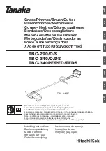
Hitachi Engine Brush Cutter/Grass Trimmer 

Models


CG 25EUAP (L) 

CG 25EUAP 

Summary of Contents for CG 25EUAP
Page 1: ...a 3 Repair flowchart 4 Repair procedure 6 Disassembly and reassembly 9 Lubrication points and type of lubricant 21 Screw tightening torque 22 Confirmation after reassembly 23 CONTENTS Page CG 25EUAP L for Europe CG 25EUAP L for the U S A and Canada CG 25EUAP LIST No CG 25EUAP F084 Apr 2016 PRODUCT NAME Hitachi Engine Brush Cutter Grass Trimmer Models CG 25EUAP L CG 25EUAP ...


Page 2: ...nspect and replace the part The high voltage cord or other cable broke or its connection is faulty Repair or replace the part The high voltage cord or other cable is grounded Repair the part The ignition coil broke or is faulty Replace the faulty part Short circuited due to foreign matter between the plug electrodes Remove the foreign matter If this problem recurs often disassemble the engine and ...

Page 3: ...valve Worn pivot Worn rocker arm Worn tappet The muffler is clogged with carbon Clean the part The air cleaner is clogged Carbon accumulated on a valve Starts but Fluctuating rpm at high speed The carburetor is clogged with foreign matter Clean the part Excessive fuel consumption The air cleaner is clogged Clean the part Chain oil is not discharged The piston ring is worn Replace the faulty part T...

Page 4: ...l in a room or other location with poor ventilation be sure to ventilate the place After repair check whether the throttle lever returns to the idling position and the engine stops when you set the stop switch to the stopping position 2 Inspection criteria Use the table below as a handy guide for inspection during and after repair and for replacement or adjustment of the spark plug Inspection item...

Page 5: ...cracked or creased Replace Air hole on tank cap is faulty Replace Pump diaphragm of carburetor is faulty Replace Carburetor is clogged with foreign matter Clean Piston ring is faulty Replace Piston ring is worn Replace Piston is worn Replace Cylinder is worn Replace Cam is damaged Replace Crank gear or cam gear is damaged Replace Valve is damaged Replace Carbon accumulated on a sealed valve surfac...

Page 6: ...pect and replace Idling speed is too low Adjust Idling speed is too low Adjust Idling speed is too high Adjust Clutch is worn or faulty Inspect and replace The speed fluctuates The engine stalls The engine stalls OK OK The speed does not increase OK Check whether the speed increases normally Check whether the engine can suddenly decelerate from high speed Check whether the cutter blade begins rota...

Page 7: ... improper adjust it Use a cloth to wipe off any fuel on the electrodes 2 Fit the Spark Plug TORCH CMR5H 18 into the Spark Plug Cap 16 and bring the electrodes into contact with a metal part of the engine In this status set the Stop Switch 164 or Stop Switch Comp 206 to the starting position and then pull the starter knob 3 When normal the electrodes of the Spark Plug TORCH CMR5H 18 generate a flic...

Page 8: ...or carburetor adjustment Idle adjust screw This screw adjusts the airflow rate at idling Turning this screw clockwise increases engine speed turning it counterclockwise decreases engine speed 2 Standard setting of carburetor Idle adjust screw 2 900 to 3 100 min 1 revolutions per minute Confirm that the cutter blade does not rotate 3 Fine adjustment Idling adjustment Turn the idle adjust screw to a...

Page 9: ...and between the Rocker Arm 34 and Intake Valve 40 to check the valve clearance Adjust the valve clearance if it is out of the range from 0 1 to 0 2 mm 7 Use a wrench to fix the lower Nut M5 29 onto the Shaft Bolt 35 In this status loosen the upper Nut M5 29 and then loosen the lower Nut M5 29 NOTE Loosening the upper Nut M5 29 without the lower Nut M5 29 being fixed will loosen the Shaft Bolt 35 T...

Page 10: ...t Then use a hand press to slowly push the shaft of Clutch Shaft 116 in order to remove the Clutch Shaft 116 while being careful not to damage the ball bearing in the Fan Case 112 2 Reassembly While holding the inner ring of the ball bearing in the Fan Case 112 slowly press fit the Clutch Shaft 116 and then mount the Retaining Ring 113 Mount Anti Vibe Rubber B 110 Pipe Holder B 109 Anti Vibe Rubbe...

Page 11: ...Muffler Gaskets A 10 and Wind Guide Plate B 11 2 Reassembly Wipe off any carbon from the exhaust inlet and outlet of the Muffler 7 or 9 and then mount the removed parts in the order shown in the figure below Tighten the Bolts M5 x 40 1 little by little alternately to prevent the Muffler 7 or 9 from being tilted 1 1 2 3 4 5 6 7 8 9 10 11 ...

Page 12: ...ner Body 72 Carburetor 26 and other parts Loosen the Bolt M5 x 30 22 and then remove the Insulator 21 and other parts 2 Reassembly Mount the removed parts in the order shown in the figure below Before mounting the Cleaner Element 80 in the Cleaner Cover 81 wash the Cleaner Element 80 with gasoline and then dry it well Cleaner carburetor and insulator 20 19 21 22 23 24 25 26 74 75 76 76 80 81 82 72...

Page 13: ...25 be careful to maintain the correct gap between the Ignition Coil 125 and the magneto rotor assembly See section 2 on page 6 Finally check that the Stop Cord 126 and the Earth Cord 124 are not damaged 5 Tank and recoil starter ass y 1 Disassembly Before removing the Tank 134 make sure that it contains no gasoline Loosen the Bolt M5 x 25 138 and then remove the Stand 136 and Tank 134 To remove th...

Page 14: ...e the Magneto Rotor 122 remove the Fly Wheel Nut 121 and then use the special magneto rotor assembly remover to pull out the Magneto Rotor 122 2 Reassembly Before mounting the Magneto Rotor 122 in the crank shaft assembly degrease the engaging sections Attach the Clutch 119 to the Magneto Rotor 122 so that the arrow mark on the side of the Clutch 119 can be seen CAUTION To prevent damage to the Pi...

Page 15: ...e 41 and Intake Valve 40 and then mount the Exhaust Valve 41 and Intake Valve 40 in Cylinder A 38 When mounting be careful not to confuse the Exhaust Valve 41 with the Intake Valve 40 While holding the Exhaust Valve 41 or Intake Valve 40 from the combustion chamber side of Cylinder A 38 to prevent either valve from falling set the Stem Seal 15 only for the Intake Valve 40 Stem Seal Base 14 only fo...

Page 16: ... 15 Cylinder rocker arm and valve 12 13 14 15 12 13 27 28 29 30 35 31 32 34 36 38 40 41 ...

Page 17: ...1 and then turn the other part of the Circlip 52 around the Piston 51 to fit the entire Circlip 52 into the groove Mount the piston rings in order of the Oil Ring 50 2nd Ring 49 and 1st Ring 48 To mount the Oil Ring 50 mount the expander first and then mount the scrapers When mounting the 2nd Ring 49 position it so that the R mark at its slit faces upward After mounting check that each piston ring...

Page 18: ...rom the mated surfaces of the Crank Case FW 59 and Crank Case ST 64 Mount the Pump Gasket 42 and Base Pump 43 to the crank case ST Mount these parts so that the chamfered section of the Inner Rotor 44 can be seen with the chamfered section facing the Cover Pump 46 Mount the Inner Rotor 44 and Outer Rotor 45 to the Base Pump 43 Apply liquid gasket Three Bond 1207C to the Base Pump 43 surface that c...

Page 19: ...pipe insertion hole on Gear Case Ass y S 180 until it contacts the end Align the hole on the side of the Main Pipe 229 with the M5 screw hole on the side of Gear Case Ass y S 180 Firmly tighten the Bolt M5 x 12 182 while confirming that it does not touch the Main Pipe 229 Tighten the Bolt M5 x 30 187 Finally make sure the Drive Shaft 230 is completely put in the pinion When the drive shaft is comp...

Page 20: ...between the engine side end of the Main Pipe 229 and the engine side end of Handle Holder B 188 is 400 mm Then secure Handle Holder C 190 by tightening the two Bolts M6 x 25 191 evenly At this time mount the Handle Holder Rubber 189 to the Main Pipe 229 with double face adhesive tape Holding the Bike Handle 175 with Handle Holder A 174 tighten the four Bolts M5 x 25 173 evenly Model CG 25EUAP 255 ...

Page 21: ...Grip 200 and Handle Clamp 203 around the Main Pipe 229 Adjust the distance between the engine side end of the Main Pipe 229 and the Handle Clamp 203 to 90 mm Then tighten the Screw M5 x 30 216 and Screw M5 x 25 204 evenly to secure the Throttle Lever Ass y 199 Mount the Loop Handle Rubber 218 to the position indicated on the level mark label on the Main Pipe 229 Then secure the Loop Handle 178 ont...

Page 22: ...ultemp PS No 2 Oil Seal 60 Molub Alloy 777 1 Shaft and spline of the Drive Shaft 230 Sliding sections of the Pivot Rocker Arm 30 and Rocker Arm 34 4 cycle oil Shafts of the Exhaust Valve 41 and Intake Valve 40 Circumference of the 1st Ring 48 2nd Ring 49 and Oil Ring 50 Sliding sections of the Pivot Rocker Arm 30 and Rocker Arm 34 Engaging surfaces of the Retainer Valve 12 Exhaust Valve 41 and Int...

Page 23: ... m Engine Crank Case ST 64 Hex Socket Hd Bolt W Washers M4 x 18 65 6 3 6 to 4 4 N m Cylinder A 38 Hex Socket Bolt W Washers M5 x 20 37 5 8 0 to 9 0 N m Muffler 7 9 Hex Socket Hd Bolt W Washer M5 x 40 1 3 6 0 to 8 5 N m Fan Case 112 Hex Socket Hd Bolt W Washers M5 x 20 115 3 2 5 to 3 5 N m Tapping Screw 101 1 1 5 to 2 5 N m Engine Cover 102 104 Tapping Screw 101 1 1 5 to 2 5 N m Tank 134 Hex Socket...

Page 24: ...mes at ambient temperature of 20 C Pull the handle more at lower temperatures 2 Confirm that each moving part functions properly and that rotating parts make no abnormal noise 3 Check the speed as follows and adjust the carburetor according to 4 Adjusting the carburetor on page 7 a Speed at full throttle for up to 30 seconds after idling for 30 seconds When attaching the cutter blade 8 000 to 10 0...

Page 25: ...3 84 1 1 2 3 4 5 6 7 8 9 10 11 10 12 12 13 13 14 15 16 17 18 19 20 19 21 22 23 24 25 26 37 38 40 41 39 27 28 29 30 31 32 33 34 35 36 42 43 44 45 46 47 48 49 50 51 52 53 52 54 55 54 56 58 57 65 85 67 68 69 70 71 70 72 73 74 75 76 78 79 80 81 82 59 60 61 61 60 62 63 64 86 87 76 ...

Page 26: ...4 16 CG 25EUAP 2 128 129 103 111 103 123 70 113 101 101 102 101 104 105 106 107 108 109 110 112 114 115 116 117 118 119 120 121 122 124 125 126 127 131 132 133 130 134 135 136 137 138 ...

Page 27: ...171 175 165 177 178 179 187 180 183 184 185 186 192 193 194 195 196 197 198 202 203 204 218 202 205 206 201 200 207 208 209 210 211 212 213 214 215 204 222 223 226 227 230 228 234 235 233 231 227 238 239 240 236 237 161 199 173 174 176 188 189 190 191 201 229 220 225 224 216 219 182 181 217 217 232 ...

Page 28: ...A 1 21 6600632 INSULATOR 1 22 6600633 HEX SOCKET HD BOLT W WASHERS M5 X 30 2 23 6600634 CARBURETOR GASKET 1 24 6600635 THROTTLE WIRE FIXING PLATE 1 25 6600636 INSULATOR GASKET B 1 26 6600637 CARBURETOR 1 27 6600621 HEX SOCKET HD BOLT W SP WASHER M4 X 10 3 28 6600620 CYLINDER HEAD COVER 1 29 6600619 NUT M5 4 30 6600617 PIVOT ROCKER ARM 2 31 6600616 PUSH ROD 2 32 6600605 TAPPET 2 33 6600622 BREATHER...

Page 29: ...1 76 6600644 SCREW W WASHERS M5 X 68 2 77 6600327 MARK PLATE T 1 FOR EUROPE 78 6600642 FUEL PIPE 1 79 6600641 PRIMING PUMP 1 80 6600647 CLEANER ELEMENT 1 81 6600645 CLEANER COVER 1 82 6600646 COVER FIXING BOLT 1 83 6699000 PRIMER LABEL 1 FOR EUROPE 84 NAME PLATE 1 85 6600665 RECOIL STARTER 1 86 6600705 BOLT WASHER D4 3 87 6600666 SEAL LOCK SCREW M4 X 25 3 101 6600691 TAPING SCREW 2 102 6600693 ENG...

Page 30: ...172 EXCEPT FOR L 162 6600832 TAPPING SCREW ST2 9 X 18 3 EXCEPT FOR L 163 6600831 HANDLE B 1 EXCEPT FOR L 164 6600833 STOP SWITCH 1 EXCEPT FOR L 165 6600830 SPRING B 1 EXCEPT FOR L 166 6600829 THROTTLE LEVER 1 EXCEPT FOR L 167 6600826 HANDLE A 1 EXCEPT FOR L 168 6600834 HEX SOCKET HD BOLT M5 X 30 1 EXCEPT FOR L 169 6600828 TRIGGER LOCKOUT 1 EXCEPT FOR L 170 6600827 SPRING A 1 EXCEPT FOR L 171 66008...

Page 31: ...51 STOP SWITCH COMP 1 FOR L 207 6600843 HANDLE CLAMP 1 FOR L 208 6600841 THROTTLE LEVER 1 FOR L 209 6600842 SPRING C 1 FOR L 210 6600849 CONNECTION LEVER 1 FOR L 211 6600847 SPRING D 1 FOR L 212 6600846 TRIGGER LOCKOUT 1 FOR L 213 6600848 SPRING E 1 FOR L 214 6600840 THROTTLE WIRE COMP 1 FOR L 215 6600845 HANDLE A 1 FOR L 216 6600844 SCREW W WASHERS M5 X 30 1 FOR L 217 6601336 LIMIT RING 2 FOR EUR...

Page 32: ...9 323210 BOLT WASHER M4 BLACK 2 FOR USA CAN 240 6685068 MACHINE SCREW W SP WASHER M4 X 12 2 FOR USA CAN DESCRIPTION REMARKS 501 6600574 BOX SPANNER 16 X 17MM 1 502 944458 HEX BAR WRENCH 4MM 1 503 6600578 CUTTER COVER 2 EXCEPT FOR L 504 6600577 BLADE 255 X 3T 1 EXCEPT FOR L 505 6600863 TOOL BAG N 1 506 6600576 SAFETY GLASSES 1 507 6600579 HANGING STRAP S 1 FOR EUROPE L 508 6600580 HANGING STRAP DE ...

Reviews: