background image

POWER TOOLS

TECHNICAL  DATA

AND

SERVICE  MANUAL

COMPOUND  SAW

  C  10FCB

SPECIFICATIONS  AND  PARTS  ARE  SUBJECT  TO  CHANGE  FOR  IMPROVEMENT

LIST No. E931

Apr. 2001

C

MODEL

C 10FCB

Summary of Contents for C 10FCB

Page 1: ...POWER TOOLS TECHNICAL DATA AND SERVICE MANUAL COMPOUND SAW C 10FCB SPECIFICATIONS AND PARTS ARE SUBJECT TO CHANGE FOR IMPROVEMENT LIST No E931 Apr 2001 C MODEL C 10FCB ...

Page 2: ...ower Limit Position 7 8 3 How to Use The Vise Assembly 8 8 4 Confirmation for Use of Sub Fence 8 8 5 Cutting Operation 9 9 ADJUSTMENT OF COMPONENTS 11 9 1 Bevel Angle Adjustment 11 10 PACKING 11 11 PRECAUTIONS IN DISASSEMBLY AND REASSEMBLY 12 11 1 Disassembly 12 11 2 Reassembly 17 11 3 Wiring Diagram 18 11 4 Lead Wire Precautions 19 11 5 No load Current 20 11 6 Reassembly Requiring Adjustment 20 1...

Page 3: ...d 4 x 4 materials at the right angle at a time without the use of a plate Capable of narrowing the clearance between the fences thanks to the adoption of the rotary sub fence 3 APPLICATIONS Cutting various types of wood workpieces Cutting workpieces of plywood decoration panels soft fiberboard and hard board Cutting aluminum sashes 4 SELLING POINTS Equipped with debris guard to restrict dispersion...

Page 4: ...ing dimension HITACHI C 10FCB Right 60 Height x Width H x W 59 x 72 2 5 16 x 2 13 16 Right and left 45 Height x Width H x W 59 x 102 2 5 16 x 4 Maker Model Max cutting dimension HITACHI C 10FCB Height x Width H x W 59 x 144 2 5 16 x 5 21 32 89 x 101 3 1 2 x 3 31 32 Table 1 Unit mm Maker Model Max cutting dimension HITACHI C 10FCB Left bevel 45 Height x Width H x W 41 x 144 1 5 8 x 5 21 32 Table 3 ...

Page 5: ... Equipped with debris guard to restrict dispersion of chips for enhanced safety in operation A debris guard has been adopted to prevent wood chips from adhering to the saw blade at the end of the cutting operation The debris guard tilts together with the saw blade during bevel cutting thereby enhancing safe operation 6 Lightweight design 14 kg in weight for easy transport in a workshop By turning ...

Page 6: ...x output No load rotation speed Cord Packaging Coating Weight Main body dimensions Width x Depth x Height 2 300 W AC single phase commutator series motor 110 V 115 V 15 A 220 V 7 8 A 230 V 7 5 A 240 V 7 2 A Type 2 conductor cabtire cable Length 2 2 m 7 2 ft Corrugated cardboard box 14 kg 31 Ibs gross weight 21 kg 46 5 Ibs 547 mm x 592 mm x 581 mm 21 17 32 x 23 5 16 x 22 7 8 4 900 min Metallic silv...

Page 7: ...em Maker Model Max cutting dimensions Height x Width H x W HITACHI C 10FCB 0 Right angle Miter right left 45 HITACHI C 10FC2 C 10FC Z 67 mm x 146 mm 2 5 8 x 5 3 4 89 mm x 92 mm 3 1 2 x 3 5 8 with aux board width 17 mm 11 16 70 mm x 146 mm 2 3 4 x 5 3 4 69 mm x 92 mm 2 3 4 x 3 5 8 59 mm x 144 mm 2 5 16 x 5 21 32 89 mm x 101 mm 3 1 2 x 3 31 32 70 mm x 105 mm 2 3 4 x 4 1 8 C 69 mm x 130 mm 2 3 4 x 5 ...

Page 8: ...nherent in the use of any power saw cannot be completely eliminated Accordingly general precautions and suggestions for the use of electric power tools and specific precautions and suggestions for the use of the compound saw are listed in the Instruction Manual to enhance the safe efficient use of the tool by the customer Salespersons must be thoroughly familiar with the contents of the Instructio...

Page 9: ... confirm that the saw blade is adjusted so that it will not cut into the table 4 Caution plate C For the U S A and Canada only 8 ADJUSTMENT AND OPERATIONAL PRECAUTIONS 8 1 Cutting A Groove on The Table Insert A groove has to be cut in the table insert before starting operation Secure a piece of wood about 5 1 2 140 mm wide to the table with the vise assembly to prevent the breakage of the table in...

Page 10: ...ssembly when it is lowered for cutting If there is any danger that it may do so loosen the 6 mm wing bolt B and move the vise assembly to a position where it will not contact the saw blade 8 4 Confirmation for Use of Sub Fence WARNING In the case of left bevel cutting turn the sub fence counterclockwise Unless it is turned counterclockwise the main body or saw blade may contact the sub fence resul...

Page 11: ...ould also cause overload and subsequent burnout of the motor On completion of the cutting operation turn the switch OFF and wait for the saw blade to come to a complete stop before raising the saw blade section head to its original position Raising the saw blade section head while the saw blade is rotating may cause unwanted cutting marks on the workpiece Techniques to avoid unwanted cutting marks...

Page 12: ...ised of these phenomena so that they understand that in cases when the cut surface may not be smooth as expected or hoped for it is not caused by the performance of the saw blade or the Model C 10FCB In the cutting examples illustrated in Fig 9 the cut surfaces on the sides marked are better than those on the sides marked 6 Compound miter bevel cutting Compound cutting can be accomplished by combi...

Page 13: ...turn table 60 clockwise 2 Mounting packings B and C Place packing C under the gear case and swing the motor section Pressing on packing C hook the stopper pin on the gear case Put the housing through the hole of packing B 3 Mounting packing A and upper packing Put the main body mounted with packings B and C in the carton box aligning with the base packing Put packing A at the left of the base Plac...

Page 14: ...the descriptions below correspond to the item numbers in the Parts List and exploded assembly diagrams CAUTION Prior to attempting disassembly or replacement of the saw blade ensure that the power cord plug is disconnected from the power source 11 1 Disassembly A Turn table and base Tools required Phillips screwdriver Flat blade screwdriver Box wrench 13 mm Box wrench 10 mm Plastic hammer Fig 15 ...

Page 15: ...and M10 x 40 3 and remove it from the Hinge 7 3 Remove the Hex Socket Set Screw M6 x 10 10 Tap the end surface of Shaft C 8 from the front of the Turn Table 38 using a flat blade screwdriver and a hammer to remove it 4 Remove the Nylon Nut M8 32 and remove the Turn Table 38 from the Base 49 5 Remove the Spacer 42 and the Table Insert 39 from the Turn Table 38 by removing each mounting screw ...

Page 16: ... 14 B Safety cover and link Spindle and spring Fig 16 Tools required Phillips screwdriver Hex bar wrench 4 mm Hex bar wrench 3 mm Box wrench 10 mm standard accessory ...

Page 17: ...er 97 and the Link 96 4 Remove the Machine Screw M5 x 20 110 and gently tap the Gear Case 85 with a plastic hammer to remove the Spindle Ass y 107 5 Remove the Hex Socket Hd Bolt M5 x 10 84 Note that the Hex Socket Hd Bolt M5 x 10 84 acts as the upper limit stopper of the Gear Case 85 and the Gear Case 85 will move upward when the Hex Socket Hd Bolt M5 x 10 84 is removed 6 Remove the Hex Socket Se...

Page 18: ...ack 83 to remove the Handle Cover 70 5 Remove the internal wires from the Switch 80 Remove two Tapping Screws W Flange D4 x 20 Black to remove the Cord 54 Cord Armor D10 7 55 and Cord Clip 65 6 Remove two Tapping Screws W SP Washer D5 x 65 to remove the Brush Terminal 68 from the Brush Holder 62 Gently tap the surface of the Housing Ass y 60 where the Gear Case 85 was mounted with a plastic hammer...

Page 19: ...r special attention should be given to the following items 1 Prior to reassembly measure the insulation resistance of the armature stator switch and other electrical components and confirm that the insulation resistance of each part is more than 5 MΩ 2 When replacing the Spring 5 apply 5 grams of Hitachi Motor Grease No 29 Code No 930035 to the inner circumference of the new Spring 5 prior to reas...

Page 20: ...tion reverse rotation or other malfunctions close attention is absolutely necessary Wiring diagram for the U S A and Canada only Fig 19 Brake coil Switch Stator coil Connector 1 Armature ass y OFF Yellow Black White Fig 20 Actual wiring diagram for the U S A and Canada only Red White Black Blue Stator ass y 3 2 Blue Yellow Red Connector ...

Page 21: ...t the lead wires are not pinched between the mating surfaces of the Housing Ass y 60 and the Handle Cover 70 Wiring diagram except the U S A and Canada Actual wiring diagram except the U S A and Canada Fig 22 Fig 21 Stator ass y Stator coil Periphery of stator core Armature ass y Black or red Red or black Red or black Black or red SW OFF 1 2 3 4 Noise suppressor It may not be provided depending on...

Page 22: ...10 V 115 V 8 A max 220 V 230 V 240 V 4 A max After disassembly or replacement of the Base 49 Turn Table 38 Fence A 46 Fence B 31 or Hinge 7 it is necessary to perform necessary adjustment to ensure that the fences are positioned at precise right angles with relation to the saw blade or dummy disc Align fence B with the saw blade or dummy disc and adjust them as necessary to ensure squareness toler...

Page 23: ...f the Knob Bolt M10 x 66 18 of the Vise Ass y 17 with machine oil 3 Swiveling section of the Turn Table 38 and the Hinge 7 Coat the swiveling and sliding portion of the Turn Table 38 and the Hinge 7 with machine oil 4 Swiveling section of the Sub Fence 27 and Fence B 31 Coat the swiveling and sliding portion of the Sub Fence 27 and Fence B 31 with machine oil 11 8 Product Precision On completion o...

Page 24: ... Black 30 130 in lbs 14 7 N m 150 kgf m Machine Screw M5 x 16 40 13 in lbs 1 5 N m 15 kgf m Machine Screw W Washers M5 x 45 Black 59 30 4 in lbs 3 4 N m 35 kgf m Hex Socket Set Screw M5 x 6 61 8 7 in lbs 1 N m 10 kgf m Tapping Screw W Flange D4 x 20 Black 66 83 14 7 in lbs 2 N m 20 kgf m Tapping Screw W SP Washer D5 x 65 69 22 6 in lbs 2 5 N m 26 kgf m Tapping Screw D4 x 10 81 13 in lbs 1 5 N m 15...

Page 25: ...Washer A 117 and Washer B 120 and repair with a file as necessary Replace Washer A 117 and Washer B 120 Loosen the Bolt W Washers M8 x 35 Black 30 and adjust the squareness Replace Fence A 46 or Fence B 31 Loosen the Bolt W Washers M8 x 35 Black 30 and adjust the squareness Replace Fence A 46 or Fence B 31 Replace the Turn Table 38 0 15 100 Dummy disc Fig 25 0 2 245 Dummy disc 0 15 100 Fig 26 0 1 ...

Page 26: ...the saw blade and inaccurate cutting i Excessive cutting force pressure is required because of dull saw blade j The workpiece moves during cutting because it is bent or deformed 1 Continued Replace Fence A 46 or Fence B 31 Check the fitting surfaces of the Hinge 7 Gear Case 85 and Shaft C 14 for any foreign substances such as cutting dust and remove it as necessary Reduce the cutting speed appropr...

Page 27: ...fects such as impact marks and scratches c Inaccurate squareness between the turn table and the saw blade causes the saw blade to cut at an improper angle and make cutting marks d Excessively fast cutting speed e Improper clamping of workpiece f The turn table is not fixed with the side handle g Loose fitting of swiveling portion of the hinge and the gear case or sluggish movement h Cutting operat...

Page 28: ...xtension cord Resharpen the saw blade Use a suitable Hitachi supplied saw blade If the saw blade has a large number of teeth the cutting resistance will be increased When using a saw blade with a large number of teeth reduce the cutting speed Correct workpiece deformation with a planer Check power supply voltage Connect the power cord to power supply Check the carbon brushes for wear Replace the c...

Page 29: ...Lever Vise Ass y Armature Ass y Fence Shaft C Base Liner Spring C Steel Ball Turn Table Hinge Fixed Cost Link Safety Cover Table Insert Guard 0 min General Assembly Cord Switch 10 min Others 20 min Link Safety Cover Stator Ass y Housing Ass y Handle Cover Cord Cord Armor Spindle Ass y Switch Lock Spring Lock Lever Gear Case Shaft B ...

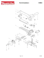
Page 30: ...ELECTRIC TOOL PARTS LIST LIST NO COMPOUND SAW Model C 10FCB 2001 4 20 E2 E931 ...

Page 31: ... 2 C 10FCB 4 01 ...

Page 32: ...9 425 WASHER M6 10 PCS 1 22 302 532 VISE PLATE 1 23 949 216 MACHINE SCREW M4X10 10 PCS 1 24 318 967 VISE SHAFT 1 25 949 556 NUT M6 10 PCS 1 26 949 432 BOLT WASHER M6 10 PCS 1 27 318 950 SUB FENCE 1 28 CAUTION PLATE A 1 29 301 806 WING BOLT M6X15 1 30 307 221 BOLT W WASHERS M8X35 BLACK 4 31 318 949 FENCE B 1 32 975 348 NYLON NUT M8 1 33 318 929 WASHER F 1 34 318 931 SCALE B 1 35 303 409 NYLOCK BOLT...

Page 33: ...BRUSH CAP 2 65 937 631 CORD CLIP 1 66 302 086 TAPPING SCREW W FLANGE D4X20 BLACK 2 67 340 473C STATOR ASS Y B 110V 1 INCLUD 68 67 340 472C STATOR ASS Y A 115V 1 INCLUD 68 67 340 473E STATOR ASS Y B 220V 230V 1 INCLUD 68 67 340 473F STATOR ASS Y B 240V 1 INCLUD 68 68 998 744 BRUSH TERMINAL 2 69 303 376 TAPPING SCREW W SP WASHER D5X65 2 70 318 960 HANDLE COVER 1 70 318 959 HANDLE COVER 1 FOR USA CAN...

Page 34: ...L ESP SUI ITA NOR SWE DEN FIN 96 318 937 LINK 1 97 998 980 SPACER 1 98 949 239 MACHINE SCREW M5X16 10 PCS 1 99 949 432 BOLT WASHER M6 10 PCS 1 100 606 ZZM BALL BEARING 606ZZC2PS2L 1 101 949 455 SPRING WASHER M6 10 PCS 1 102 949 258 MACHINE SCREW M6X20 10 PCS 1 103 949 432 BOLT WASHER M6 10 PCS 1 FOR USA CAN AUS FRG AUT GBR FRA HOL BEL ESP SUI ITA NOR SWE DEN FIN 104 301 806 WING BOLT M6X15 1 FOR U...

Page 35: ... WASHER 1 122 996 258 BOLT LEFT HAND M7X17 5 1 123 949 567 LOCK NUT M6 10 PCS 1 124 949 454 SPRING WASHER M5 10 PCS 2 FOR CHN FRG AUT GBR FRA HOL BEL ESP SUI ITA NOR SWE DEN FIN 701 976 478 DUST BAG 1 702 940 543 BOX WRENCH 10MM 1 703 998 834 HOLDER 2 704 318 968 STOPPER 1 705 301 806 WING BOLT M6X15 1 901 976 472 TCT SAW BLADE CROSS CUT 255MM D15 9 HOLE 1 902 976 473 TCT SAW BLADE 255MM D15 9 HOL...

Page 36: ......

Reviews: