


SPECIFICATIONS AND PARTS ARE SUBJECT TO CHANGE FOR IMPROVEMENT.
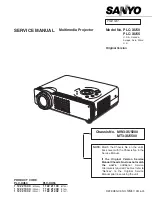
Multimedia LCD Projector
November 2007
SM
0599
CP-A100(A1DN)
ED-A100(A1DN)
ED-A110(A1DN)
SERVICE MANUAL
Be sure to read this manual before servicing. To assure safety from fire, electric shock, injury, harmful
radiation and materials, various measures are provided in this Hitachi Multimedia LCD Projector.
Be sure to read cautionary items described in the manual to maintain safety before servicing.
Caution
1. When replac
ing
the lamp, avoid burns to your fingers
, t
he lamp becomes
very
hot.
2. Never touch the lamp bulb with a finger or anything else. Never drop it or give it a shock.
It
may
cause bursting of the bulb.
3. This projector is provided with a high voltage circuit for the lamp. Do not touch the electric parts of
the
power unit (circuit)
or the
power unit (ballast) after turn
ing
on the projector.
4. Do not touch the exhaust fan during operation.
5. The LCD module assembly is likely to be damaged. If replacing the LCD PRISM assembly, do
not hold the FPC of the LCD module assembly.
6. Use the cables which are included with the projector or
as
specified.
Service Warning
Warning
The technical information and parts shown in this
manual are not to be used for: the development,
design, production, storage or use of nuclear, chemical,
biological or missile weapons or other weapons of
mass destruction; or military purposes; or purposes that
endanger global safety and peace. Moreover, do not
sell, give, or export these items, or grant permission for
use to parties with such objectives. Forward all inquiries
to Hitachi Ltd.
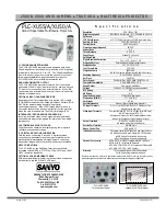
1. Features
------------------------------------------------------ 2
2. Specifi cations ----------------------------------------------- 2
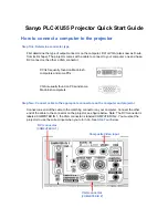
3. Names of each part ---------------------------------------- 3
4. Adjustment
--------------------------------------------------- 6
5. Troubleshooting ------------------------------------------ 14
6. Service points
--------------------------------------------- 22
7. Wiring diagram
-------------------------------------------- 40
8. Disassembly diagram ----------------------------------- 54
9. Replacement parts list ---------------------------------- 70
10. RS-232C communication ------------------------------ 73
11. Block diagram --------------------------------------------- 88
12. Connector connection diagram ----------------------- 89
13. Basic circuit diagram ------------------------------------ 90
Contents
Summary of Contents for A1DN
Page 14: ...14 CP A100 ED A100 ED A110 A1DN 5 Troubleshooting Check points ...
Page 71: ...THIS PAGE INTENTIONALLY LEFT BLANK 71 ...
Page 72: ...72 MEMO ...
Page 92: ...92 CP A100 ED A100 ED A110 A1DN MEMO ...
Page 93: ...CP A100 ED A100 ED A110 A1DN 1 2 3 4 5 6 1 2 3 4 5 6 A B C D E F G POWER UNIT BALLAST 1 ...
Page 94: ...CP A100 ED A100 ED A110 A1DN 1 2 3 4 5 6 1 2 3 4 5 6 A B C D E F G POWER UNIT BALLAST 2 ...
Page 95: ...CP A100 ED A100 ED A110 A1DN 1 2 3 4 5 6 1 2 3 4 5 6 A B C D E F G POWER UNIT CIRCUIT 1 ...
Page 96: ...CP A100 ED A100 ED A110 A1DN 1 2 3 4 5 6 1 2 3 4 5 6 A B C D E F G POWER UNIT CIRCUIT 2 ...