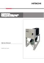
background image

RCME-(40-70)WH1

Service Manual

SAMURAI SERIES

WATER COOLED WATER CHILLERS

-MODULAR-R134a-SCREW TYPE-

Summary of Contents for 8E040341

Page 1: ...RCME 40 70 WH1 Service Manual SAMURAI SERIES WATER COOLED WATER CHILLERS MODULAR R134a SCREW TYPE ...

Page 2: ......

Page 3: ...Contents SMGB0120 rev 0 11 2017 I 1 2 3 4 General information Control Functions Servicing Troubleshooting Co n tents ...

Page 4: ......

Page 5: ... 21 2 1 10 2 temperature setting function 22 2 1 11 External thermo operation from external contact 23 2 1 12 Water Temperature of the Control Target 25 2 1 13 Operation from DC24V contact input 26 2 1 14 Thermo OFF function selection 31 2 1 15 Selection of enabling disabling of alarm release by means of remote stop 32 2 1 16 Limitation setting for pump feedback waiting time 33 2 1 17 Inlet water ...

Page 6: ...ment of the pressure sensor PSW 74 3 3 14 Replacement of the pressure relief valve 74 3 3 15 Replacement of the sight glass 74 3 3 16 Replacement of the stop valve x3 74 3 3 17 Repalacement of the thermistor Suction THMs 75 3 3 18 Replacement of the thermistor Discharge THMd 75 3 3 19 Replacement of the crankcase heater CH 75 3 3 20 Replacement of the thermistor Evaporation THMe 76 3 3 21 Replacem...

Page 7: ...n control function 92 4 5 Alarm indication 93 4 6 Summary of fault diagnosis 94 4 7 Method for fault diagnosis 96 4 8 Troubleshooting by alarm code 97 4 9 Analysis and countermeasure of abnormalities 121 4 10 Thermistor characteristics 127 4 10 1 Thermistor temperature characteristics All temperature except discharge gas 127 4 10 2 Thermistor temperature characteristics for discharge gas temperatu...

Page 8: ......

Page 9: ...rev 0 11 2017 1 1 1 General information Index 1 1 General notes 2 1 2 Safety and applied symbols 3 1 2 1 Norms and Regulations 3 1 3 Product guide 4 1 3 1 Classification of water chiller models 4 1 3 2 Product guide Water chillers 4 ...

Page 10: ...ations and descriptions included in this document No type of modification must be made to the equipment without prior written authorisation from the manufacturer HITACHI pursues a policy of continuing improvement in design and performance of products The right is therefore reserved to vary specifications without notice HITACHI cannot anticipate every possible circumstance that might involve a pote...

Page 11: ...ng the caution symbol you can also find information on safe procedures during unit installation NOTE The text following this symbol contains information or instructions that may be of use or that require a more thorough explanation Instructions regarding inspections to be made on unit parts or systems may also be included 1 2 1 Norms and Regulations Appropriate refrigerant The refrigerant used in ...

Page 12: ...ic modules Unit type Modular water chiller RCM E Made in Europe Position separating hyphen fixed Capacity HP 40 50 60 70 W Water cooled H R134a refrigerant Serie RCM E XX W H 1 1 3 2 Product guide Water chillers Basic modules 3N 400V 50Hz Unit Code RCME 40WH1 8E040341 RCME 50WH1 8E050341 RCME 60WH1 8E060341 RCME 70WH1 8E070341 ...

Page 13: ...contact input 26 2 1 14 Thermo OFF function selection 31 2 1 15 Selection of enabling disabling of alarm release by means of remote stop 32 2 1 16 Limitation setting for pump feedback waiting time 33 2 1 17 Inlet water temperature thermo OFF function 34 2 2 Control of the cooling cycle 36 2 2 1 Compressor Control 36 2 2 2 Expansion Valve Control 37 2 2 3 Overcurrent protection control 39 2 3 Contr...

Page 14: ...p will be different Compressor Control Once that Compressor delay time has passed after pump startup compressor starts up with Υ Δ control performs startup unload control during 60 seconds and then shifts to capacity control The settings of Compressor delay time can be changed in the range between 30 seconds and 10 minutes in 30 second steps Set a delay time adjusted to the characteristics of the ...

Page 15: ... remote stop alarm clear Option It is possible to disable the release of alarms by remote stop order input NOTE Normally alarms can be released by stop control from either remote or the main unit Since this function is optional it is necessary to make the settings for the enabling of this function at the time of local installation Limit of waiting time for pump feedback Option It is possible to de...

Page 16: ...n red alarm orange Remote display Outputs operation of the chiller unit cool heat mode pump operation alarm warning and defrosting Control of Master Slave group Module Control Option When installing multiple units operation as one entire heat system is possible by connecting each chiller unit through H LINK It is possible to connect a maximum of 8 units to one group NOTE Since this function is opt...

Page 17: ...t Thermo OFF and re start at T2 Load up I zone Load up II zone Load Down zone Thermo off zone Load up I status Load up II status Neutral status Load down status Stop status Load up II status Neutral status Neutral status Neutral zone Starting setting example Method of outlet temperature detection 1 Load up I control at over 9 C The capacity is changed a lot in order to approximate the target temp ...

Page 18: ...ings locally depending on usage purpose but since the necessary volume of water will change change the settings only upon confirmation of the amount of the retained volume of water in the entire local system Output Cycle Load up I Output time Load up II Output time Load down Output time Setting range Seconds 10 120 Default 30 10 120 Default 10 2 120 Default 2 2 120 Default 2 Step Seconds 10 1 1 1 ...

Page 19: ... with the setting temperature currently enabled is illuminated INPUT NOTE Set1 This is the setting value of the master chiller unit and water temperature control is normally performed against this setting value Set2 This is the setting value when 2 temperature setting function is enabled Ext The setting value from an external source is displayed such as when a slave unit following the setting of t...

Page 20: ...ter temperature control settings Display the input window with INPUT key Input the setting value with up and down keys Register the input value and close the window by pressing the ENT key Also by pressing the CAN key the input value is not registered and the window is closed Continuous control type ...

Page 21: ...old water flow 2 Normal Operation is performed with the smallest load for 1 minute after compressor startup After finishing startup control control is shifted to normal water temperature control 3 Stop a At Themo OFF Continuous control type stops suddenly At this time the compressor sounds as if it was counter rotating due to the pressure differential between high and low pressure b Upon alarm inc...

Page 22: ...etting method of compressor delay time Display the input window with INPUT key Input the setting value with up and down keys Register the input value and close the window by pressing the ENT key Also by pressing the CAN key the input value is not registered and the window is closed ...

Page 23: ...tion is not selected it is necessary to restart operation Power failure exceeding 2 seconds Power source status ON OFF ON OFF ON OFF ON OFF Pump operation order Chiller unit operation status Compressor operation status min min Time guard Time guard Selected from DIP switches NOTE When this function is enabled recovery upon restoration of the power supply returns to the state before the power inter...

Page 24: ...IP switches DSW3 1 3 2 3 3 are used for address setting when using the functions to control the number of units but the addition of time to the 3 minutes guard is effective even if these functions are not used In this case it is not necessary to connect transmission cables between each chiller unit Unit number DSW3 PCBA Added time 1 2 3 4 1 OFF OFF OFF OFF 0 s 2 OFF OFF ON OFF 5 s 3 OFF ON OFF OFF...

Page 25: ...t with orders from the local control panel by means of peak cut etc or to restrain the maximum limit of compressor operating capacity Since it also allows to force a change of the operation capacity in response to the load of the facility it is a convenient function to perform temperature control from the local control panel Forced thermo OFF function a Contents of activation When it is required t...

Page 26: ...e LCD screen The selection to enable or release the setting value is performed with the order signal from the local control board Also the overcurrent protection control is always enabled even in a state where this function is disabled b Setting method when cooling mode is set Display the input window with INPUT key Input the setting value with up and down keys Confirm with ENT key Cancel with CAN...

Page 27: ...ndow with INPUT key Input the setting value with up and down keys Confirm with ENT key Cancel with CAN key In case of cooling heating mode NOTE Input the ratio corresponding to the Standard current value displayed on the LCD screen Confirm the setting value displayed on Current limitation setting value This control becomes disabled when selecting 100 ...

Page 28: ...unction to control the number of units however excluding the connection to group controller arrange the wiring to unit number 1 master unit This function becomes enabled in all the units when inputting the signal to unit number 1 setting value is also common with the setting value of unit number 1 Signal input to chiller units with address settings between unit number 2 and 8 are invalid In case o...

Page 29: ...Control board of the chiller unit Forced load up switch Power source of the local control board NOTE Thermo OFF judgement protection devices and protection control from the setting temperature of the main unit are always enabled and this control gives them priority When using the function to control the number of units however excluding the connection to group controller arrange the wiring to unit...

Page 30: ... Temp Set2 on the water temperature setting screen is illuminated to indicate that the 2 temperature setting has become enabled 9 Disabled 2 temperature settings enabled NOTE Before operating the chiller unit select which temperature to use as setting temperature from the 1st and the 2nd switch selection then operate the chiller unit it is possible to switch during operation but it may cause insta...

Page 31: ...d forced load operation thermal storage operation is shown 5 6 7 24 25 2 0V 3 2 0V 3 SW2 SW2 Remove the wiring between 5 and 6 if it is connected Local Switch PBSR2 OFF PBSR1 OFF Thermal storage Switch between air conditioning and thermal storage Thermal storage Forced load operation switch Air conditioning Air conditioning Time chart Forced load operation switch Chiller unit Keep more than 5 minu...

Page 32: ...ernal thermo set the external thermo to activate before the thermo OFF temperature of the main unit In case of stop by thermo OFF temperature of the main unit operation restarts automatically When performing thermal storage from the main unit thermo it is possible to prevent restart by turning the pump OFF with optional function Pump operation in ON OFF Cont Setting method Select OFF COOL COOL HEA...

Page 33: ...ter Temperature of the Control Target It is possible to select which water temperature to use for capacity control and thermo OFF judgement either Inlet or Outlet Use the outlet water temperature factory default setting in normal conditions Setting method COOL COOL HEAT Select IN Select IN ...

Page 34: ...lable only in remote mode during independent operation of the chiller unit Level input a Signal aspect and basic sequence For wiring 9 Terminal board Section arranged as a local work Alarm output DC24V less than 0 8A Relay coil for DC24V etc to be prepared locally The relay coil is powered on in case of alarm Do not connect a LED or a relay of internal diode type Run stop switch to be prepared loc...

Page 35: ...0 rev 0 11 2017 27 2 b Setting method COOL COOL HEAT NOTE Do not bundle the additional wiring together with other control circuits and in particular with wiring for 230V or 400V Put the additional wiring separately inside a metallic pipe or use a shielded wire ...

Page 36: ...l work Alarm output DC24V less than 0 8A Relay coil for DC24V etc to be prepared locally The relay coil is powered on in case of alarm Do not connect a LED or a relay of internal diode type Time chart Switch Keep more than 5 minutes More than 200ms More than 200ms ON OFF Run Stop Chiller unit NOTE Pulse input indicates an ON input of the same switch when changing the status of the chiller unit as ...

Page 37: ...17 29 2 b Setting method COOL COOL HEAT Select Pulse Select Pulse NOTE Do not bundle the additional wiring together with other control circuits and in particular with wiring for 230V or 400V Put the additional wiring separately inside a metallic pipe or use a shielded wire ...

Page 38: ...nged locally field supplied Time chart 5 5 5 5 ON OFF ON ON Run Stop Unit More than 5 min More than 200 ms ON OFF Run Stop b Setting method Since it applies remote control it is not required to change any settings at the LCD screen NOTE Do not bundle the additional wiring together with other control circuits and in particular with wiring for 230V or 400V Put the additional wiring separately inside...

Page 39: ...ure Example of thermo OFF judgement extension 7 6 Inlet water temperature Outlet water temperature 10 minutes Does not stop immediately even if temperature becomes lower than thermo OFF temperature Stop with 10 continued minutes below thermo OFF temperature This function is used in cases in which the water flow is reduced temporarily such as when opening and closing the valves installed in the wat...

Page 40: ...e that the chiller unit has stopped due to an alarm is achieved by stop control it is possible to stop both from the stop button of the main unit or from remote stop control But it is possible to configure this alarm release to make it valid only from the stop button on the main unit alarm cannot be released by remote stop control This function is valid for places where there is a remote device fo...

Page 41: ...case that there is no input of pump feedback signal between and or when the difference between inlet and outlet temperature of cold water is too large This function shifts to Alarm in case that the state of continues for a certain amount of time Initial value for the standard specification Unlimited Initial value for the specification with pump mounted 5 minutes Setting range 1 30 minutes The disp...

Page 42: ...nabling this setting the judgement of thermo OFF is carried out also from inlet water temperature Thermo OFF judgement by outlet water temperature is also enabled Water temperature control is carried out from outlet water temperature even in case that this function is enabled It is effective when there is the need to set thermo OFF with the return water temperature from the load Setting method COO...

Page 43: ...ng and heating operation It is also possible to switch the setting values with 2 1 10 2 temperature setting function Thermo ON conditions are the same as in normal outlet water temperature control It can be set for both cooling and heating operation It is also possible to switch the setting values with 2 1 10 2 temperature setting function Display the input window with INPUT key Input the setting ...

Page 44: ...tion In the case of load up Suction gas Discharge gas To suction side Slide valve Rotor Oil supply Solenoid valve 202 Solenoid valve 203 Solenoid valve 201 To suction side Cylinder part Piston Rod Spring Oil supply In case of load down Suction gas Bypass Discharge gas To suction side Slide valve Rotor Oil supply Solenoid valve 202 Solenoid valve 203 Solenoid valve 201 To suction side Cylinder part...

Page 45: ...peration information of the LCD screen displays Adjusting 0 zero point of the expansion valve while the segment display becomes Cn E0 n stands for unit number Startup control I The opening is predetermined for 1 minute after compressor startup Startup control II The opening is controlled within a predetermined amount of variation until the discharge gas superheat TdSH which is calculated from the ...

Page 46: ...the valve is forced to open and momentarily set somewhat open in comparison with the opening under normal control e Forced control In case of continued conditions of suction gas superheat higher than 8ºC with a cold water output setting temperature higher than 25ºC the valve is forced to open and momentarily set somewhat open in comparison with the opening under normal control f 0 zero point adjus...

Page 47: ... is possible to change the setting value of overcurrent protection control from the Service menu Activation of overcurrent protection When the running current of the unit reaches the upper limit of running current the power source capacity load is abated by means of forced unload operation See figure below Load down control is continued until reaching 98 of setting value for current limit Load up ...

Page 48: ... transmission wires b Setting of terminal resistance Perform the setting of the terminal resistance Choose one unit which may be any from unit 1 to 8 and switch ON up DSW7 1 of its CPU PCB PCBC c Setting of address For all the chiller units in the same group configure address settings Set the addresses in ascending order without leaving gaps Example Set unit numbers from 1 to 5 if there are 5 unit...

Page 49: ...n the case of standalone operation of the Chiller Unit 2 Pump Interlock Wiring Required Input the feedback signal of the pump to all the chiller units also necessary in the case of batch pump Chiller units without pump feedback signal input will not operate Pump feedback signal 3 Pump operation order wiring Not required for specifications with pump mounted Connect the wiring since pump operation s...

Page 50: ...n in order to regain the target of the control of Master Slave group Also in case of using it to reset an alarm it is necessary to enable the optional function LCD screen setting Remote stop reset at each of the chiller units 5 5 Forced stop signal Alarm reset System recovery signal Remove the connection between 5 and 6 5 5 System recovery signal Forced stop Alarm reset signal 5 More than 200ms ON...

Page 51: ...t event occurs 2 About recovery method to system from detachment state Modules that have been once detached are not subject to the control of Master Slave group unless performing recovery operation However modules that have become detached because of transmission abnormality are recovered automatically as soon as transmission is restored Perform recovery operation after removing the causes of the ...

Page 52: ...ut performing the control of Master Slave group Possible in 1 pump systems only NOTE Setting method In 1 pump system settings set both waiting time for effect of addition and waiting time for effect of reduction to 0 Practical operation 1 At system start up First one chiller unit with the highest priority order is started up and thermo ON OFF judgement is conducted When the conditions to start up ...

Page 53: ...es that can be operated at the same time Minimum number of operating units Sets the minimum number of modules to be operated at light load operation Pump operation Selects batch or individual When selecting individual pump operation order is linked to the run stop of the module When selecting batch all the modules which are target of the control of group Master Slave during system operation set pu...

Page 54: ...nd confirmation of operation conditions through the LCD screen In the case of master unit unit 1 setting In the case of slave unit units 2 to 8 setting Set the setting temperature difference when the 1st water temperature setting is enabled Set the setting temperature difference when the 2nd water temperature setting is enabled If there are more than 5 units connected shift to priority setting scr...

Page 55: ...2 Control Functions Control of Master Slave group SMGB0120 rev 0 11 2017 47 2 Status screen of the control of Master Slave group ...

Page 56: ... remotely SW2 Local Remote 3 Cooling Heating switch Selects between cooling and heating when in local control setting This switch allows the unit to work in only cooling mode when cooling is enabled or in cooling heating mode when heating is enabled SW3 Cooling Heating 4 ON OFF button Performs as ON button for operation when in local control setting The OFF button is always enabled regardless of l...

Page 57: ...ster module such as during test run or in servicing Operation order Stop order Press the Stop button Close the door inside the electrical parts box Close the door inside the electrical parts box Close the door inside the electrical parts box then close the door of the electrical parts box Open the door inside the electrical parts box Preparations for remote control complete Open the door of the el...

Page 58: ...ration display Remote Operation display Main unit Operation display Remote Alarm display Main unit Alarm display Remote Alarm display Remote Operation status Pump Stop ON OFF ON OFF ON OFF ON OFF ON OFF ON OFF ON OFF ON OFF ON OFF ON OFF ON OFF ON OFF ON OFF Run Run Stop Stop Unit Contact for formation of self holding Electronic expansion valve Compressor 6C1 Compressor 52C1 Compressor 42C1 Protec...

Page 59: ...essure sensor PSW 74 3 3 14 Replacement of the pressure relief valve 74 3 3 15 Replacement of the sight glass 74 3 3 16 Replacement of the stop valve x3 74 3 3 17 Repalacement of the thermistor Suction THMs 75 3 3 18 Replacement of the thermistor Discharge THMd 75 3 3 19 Replacement of the crankcase heater CH 75 3 3 20 Replacement of the thermistor Evaporation THMe 76 3 3 21 Replacement of the the...

Page 60: ...120 rev 0 11 2017 52 3 4 7 Transformers TF2 TF3 TF4 83 3 4 8 Overcurrent relay ORC 83 3 4 9 Contactors CMC CMCD CMCS 84 3 4 10 Fuses EF1 EF2 EF3 EFR EFS EFT 84 3 4 11 Fuses PFC 85 3 4 12 Relays 86 3 4 13 Main Switch 87 ...

Page 61: ...for a factory purpose only and an additional password is required NOTE Acces password for authorized personnel only Password 1225 2 sec Latest version will be shown MAIN SCREEN MENU Pictogram description Back to main menu Back to main screen menu Next screen Previous Screen INPUT SCREEN EXAMPLE NOTE This screen will be shown after clicking on the INPUT button Increases the value Decreases the valu...

Page 62: ...3 Servicing LCD display for Service Menu SMGB0120 rev 0 11 2017 54 Auto expansion valve initialize SERVICE MENU SCREEN 1 2 Superheat setting SERVICE MENU SCREEN 1 2 ...

Page 63: ...3 Servicing LCD display for Service Menu SMGB0120 rev 0 11 2017 55 3 Expansion valve manual operation SERVICE MENU SCREEN 1 2 Overcurrent protection setting SERVICE MENU SCREEN 1 2 ...

Page 64: ...17 56 Sensor adjust SERVICE MENU SCREEN 1 2 NOTE When a sensor is giving a different value than the actual value a correction can be set Example Real temperature 25 0ºC Thermistor value 24 0ºC Input 1 0ºC the correction value System recognizes as 24 0 1 0 25 0ºC ...

Page 65: ...Comp Hr Setting NOTE When PCBc is replaced the previous information related to compressor operating time and number of restarts can be entered from the service menu SERVICE MENU SCREEN 1 2 Confirm DSW set SERVICE MENU SCREEN 1 2 NOTE This function is not yet implemented ...

Page 66: ...3 Servicing LCD display for Service Menu SMGB0120 rev 0 11 2017 58 4 20 mA input SERVICE MENU SCREEN 2 2 Continuous control SERVICE MENU SCREEN 2 2 Order dissable SERVICE MENU SCREEN 2 2 ...

Page 67: ...n resets all data and returns to the initial values except for the warning and alert history and accumulated operating time period and operating time of the compressor When a wrong DIP switch DSW setting is performed do an initialization after set the DIP switch DSW correctly SERVICE MENU SCREEN 2 2 ...

Page 68: ...3 Servicing LCD display for Service Menu SMGB0120 rev 0 11 2017 60 Delete log NOTE This function deletes the stored data concerning to the alarms and cautions SERVICE MENU SCREEN 2 2 ...

Page 69: ...es security gloves it is a must to wear convenient eye protection NOTE The images and pictures shown in this chapter except when the contrary is indicated correspond to the RCME 50WH1 model Processes described are equally valid to all RCME WH1 models NOTE When brazing operations are required check to ensure whether there are flammable materials around when using the burner for pipe connections Oil...

Page 70: ...igh temperature Access inside the module for servicing can be easily done The unit is open except the electrical box and the inner parts are easily accessible 3 3 1 Compressor removal When Removing the Compressor Remove the compressor while completing the following procedures 1 Before any other operation collect all refrigerant as described in chapter Recovering the refrigerant by Pump down proced...

Page 71: ... metallic band which fixes the Thermistor Softly pull the thermistor backwards Thermistor THMs Screw 5 Remove all the wiring of the compressor a Power supply wiring Power supply cable hose R S T b Control wiring connector QCN4 and Pd and Ps cables QCN13 Connector QCN4 Connector QCN13 ...

Page 72: ...shown in the picture Screws x8 Right side From E Box Left side From E Box 7 Remove the U rod fix to the structure Screw U Rod 8 Use a portable crane or a lift truck to remove the compressor Introduce the forks under the compressor supports and gently pull backwards CAUTION Compressor is heavy two persons and a portable crane or similar are required ...

Page 73: ...ecting part flange of compressor and the upper cover of oil separator Do not separate high pressure part between the check valve and the projecting part flange of compressor as collected refrigerant would be spilled out Low pressure side Disconnect from this part High pressure side Disconnect from this part Upper cover of oil separator Projecting part flange of compressor Check valve Do not remove...

Page 74: ...of finding any abnormality such as dirt or any damage clean or replace the part as adequate 5 Oil charge work Attach the oil strainer the oil strainer cover C and the oil extraction plugs A B Connect the charge hose to the check joint Discharge pressure outlet Let the oil be absorbed by the charge hose while performing vacuum from the check joint of the suction side Charge the amount of oil that h...

Page 75: ...f the unit and wait 15 min until hot parts become cool g After these works above almost all refrigerant is collected in the condenser h Recover the rest of refrigerant from the water cooler and the compressor connecting a hose to the check joint and a vacuum and collect the rest of refrigerant into a tank With a vacuum pump a Completely close the stop valve b Connect the gauge manifold using charg...

Page 76: ...t never use chains or metallic ropes to lift the condenser as they can damage the condenser 5 Unscrew the 4 screw of the foot plate heat exchanger 4 Screws 2 foot plate exchanger supports 6 Remove the condenser Softly lift the condenser and place it on a strong and stable surface CAUTION In spite of water shut off valves are closed water inside the plate heat exchanger and water pipe remain CAUTIO...

Page 77: ...ic connections 3 Screw eyebolts to both sides of the cooler to the bolts for that purpose Fasten a textile belt to proceed to lift the cooler CAUTION Do not never use chains or metallic ropes to lift the cooler as they can damage the cooler 4 Unscrew the 4 screw of the foot plate heat exchanger 2 Screws 2 Screws 5 Remove de cooler Softly lift the cooler and place it on a strong and stable surface ...

Page 78: ... expansion valve a This unit uses an electronic expansion valve which is normally closed when the compressor stops For this reason when the valve upstream of the expansion valve liquid outlet valve of the heat exchanger is closed refrigerant may accumulate between the liquid outlet valve of the heat exchanger and the expansion valve In case of removing the brazed part of the expansion valve always...

Page 79: ... replacing the solid core perform the procedure in the reverse order than removing NOTE At reassembling oil or grease the top cover gasket and the thread of the cover screws 1 2 3 4 5 6 7 8 9 Filter drier unit replacement Replace the filter drier unit if any leakage or malfunction is detected Proceed following the steps explained below 1 Protect the surroundings of the unit from the heat of the bl...

Page 80: ...crew Plastic bands 2 Remove the 4 screws of the inlet pipe flange Inlet pipe flange 4 Screws Thermistor THMd 3 Remove the 4 screws that fixes the check valve to its location at the discharge outlet 4 Remove the 4 Allen screws that fixes the cover of the check valve Once disassembled 5 Remove the cover of the check valve to protect the inner parts from the heat of the blowtorch when disassembling t...

Page 81: ...nd proceed to its replacement 4 When reassembling proceed in reverse order than removing High pressure switch PSH Clamp Screw 3 3 11 Replacement of the pressure sensor Pd 1 Disconnect the cables 4 5 and 6 of the pressure sensor from the E box of the compressor terminal board 2 Remove the screw of the clamp that fixes the switch 3 Unscrew the switch and proceed to its replacement 4 When reassemblin...

Page 82: ... 3 3 15 Replacement of the sight glass To remove the sight glass proceed as follows 1 Remove the brazed parts using a blowtorch and previously cooling the pipe side and the sight glass with wet cloth in order to avoid brazing material enter inside the pipes 2 When reassembling after replacing the sight glass perform the procedure in the reverse order than removing Sight glass Brazed parts 3 3 16 R...

Page 83: ...ation of the discharge pipe thermistor THMd 2 Loosen the screw fixing the thermistor 3 At the E box disconnect the CN26TD contact or the Faston terminals 9 and 10 of multiple contact QCN3 4 Remove the thermistor 5 When reassembling after replacing the thermistor THMd perform the procedure in the reverse order than removing Discharge pipe Thermistor THMd Thermistor THMd Screw Plastic bands 3 3 19 R...

Page 84: ... order than removing Thermistor THMe Evaporation pipe Thermistor THMe Screw Plastic bands 3 3 21 Replacement of the thermistor Cooler water inlet THMwi 1 Unscrew the nut of the cable gland 2 Gently pull the sensor wiring upwards CAUTION Sensor sheath is full of sealing silicone Use gloves and eye goggles for protection in order to avoid possible injuries to eyes and skin 3 Disconnect the 3 and 1 F...

Page 85: ...o proceed as follows 1 Unscrew the nut of the cable gland 2 Gently pull the sensor wiring upwards CAUTION Sensor sheath is full of sealing silicone Use gloves and eye goggles for protection in order to avoid possible injuries to eyes and skin 3 Disconnect the 3 and 1 Faston terminals or the CN5 connector at the E box 4 Replace the thermistor in reverse order than removing NOTE Use sealant silicone...

Page 86: ...door first 3 4 2 Removal of the LCD screen The removal of the LCD screen have to be done from the inner of the left door at the E box 1 Remove the wirings a Remove the COM2 connector Using a flat screwdriver loosen the 2 screws of the COM2 port connector and pull backwards the connector b Remove the DC24V connector by pulling backwards COM2 port connector LCD power supply connector 2 Using a Phill...

Page 87: ...ns 1 Remove the wirings connected to the push button using a Phillips screwdriver 2 Remove the nut fixing the push button holder to the E box door 3 Replace the push button and proceed to assembly in reverse order than removing Phillips screws x2 Nut 3 4 4 Access to electrical components PCB s are placed on 2 levels into the E box By simply opening the left door there is the PCBd In a second level...

Page 88: ...r PCBc Fuses Relays Access to second level electric components To have acces to the main control and power components of the unit into the E box follow the next steps Fixation assembly 1 Firmly pull the plate 2 Pull until release the fixation assembly 3 Keep pulling until the plate is in horizontal at the top ...

Page 89: ...egment display Pressure switches PSW PSW3 PSW4 PSW5 PSW6 Pressure switches PSW PSW1 PSW2 Switches SW SW1 SW2 DSW1 DSW2 DSW3 DSW4 DSW5 DSW6 Dip switches PSW Rotary switches RSW1 Plastic holder Plastic holder Plastic holder a Remove the PCB by pressing the expanded part of the 4 plastic holders using long nose pliers as shown in the picture below b Pull the PCB out from the PCB plate ...

Page 90: ... expanded part of the 4 plastic holders using long nose pliers as shown in the picture below b Pull the PCB out from the PCB plate PCBd Plastic holder Plastic holder a Remove the PCB by pressing the expanded part of the 4 plastic holders using long nose pliers as shown in the picture below b Pull the PCB out from the PCB plate ...

Page 91: ...mers TF2 TF3 TF4 To remove any of the TF2 3 or 4 simply open left door of the E box and follow the next steps according to the transformer to remove 1 Remove all the wirings corresponding to the transformer to remove As shown the image 2 Remove the 2 screws that fix the transformer to the plate Screws Screws to PCN239 to CN56 to PCN238 to CN55 to PCN240 to CN57 3 4 8 Overcurrent relay ORC To remov...

Page 92: ...low the steps described below 1 Remove all the wiring with a Phillips screwdriver 2 Remove the screws that fixes the contactors to the plate 3 When reassembling proceed in reverse order than removing Screws Use a Phillips screwdriver to remove the screws 2 screws at the top and 1 screw at the bottom 3 4 10 Fuses EF1 EF2 EF3 EFR EFS EFT EF fuse series are mounted on DIN rail To replace any damaged ...

Page 93: ...s replacement following the next steps 1 Open the plastic cover that protects the fuse 2 Take the fuse puller tool a Push the red button b Slide the fuse puller tool up or down c Pull the fuse puller backwards 3 On the damaged fuse put the fuse puller tool and firmly push to fix the tool on the fuse Once the fuse is trapped pull the tool backwards ...

Page 94: ...ews and replace the fuse holder 3 3 Flat screw driver or 13mm spanner PFC1 1 PFC3 6 PFC2 4 PFC1 2 PFC3 5 PFC2 3 2 Phillips screwdriver 4 When reassembling perform the procedure in the reverse order than removing 3 4 12 Relays To remove any of the relays proceed as follows 1 Detach the Faston terminal from its connection 2 Remove the 2 screws fixing the relay to the plate 3 Replace the relay Faston...

Page 95: ...teps 1 Turn the switch off in order to be able to open the E box door 2 Open the E box door 3 Remove the wiring Unscrew the nuts from the terminals with a 13 mm spanner 4 Remove the 4 screws with a flat screwdriver 5 When reassembling proceed in the reverse order than removing T MIT L3 R MIR L1 S MIS L2 4 flat screws MIT L3 ...

Page 96: ......

Page 97: ... 4 6 Summary of fault diagnosis 94 4 7 Method for fault diagnosis 96 4 8 Troubleshooting by alarm code 97 4 9 Analysis and countermeasure of abnormalities 121 4 10 Thermistor characteristics 127 4 10 1 Thermistor temperature characteristics All temperature except discharge gas 127 4 10 2 Thermistor temperature characteristics for discharge gas temperature 127 4 11 Pressure sensor characteristics 1...

Page 98: ... on the transformer is being output Voltage and circuit 30 0V 230V 15 5V 16 1V PCN2A CPU PCB 5 3 T1 Red White Internal transformer of the unit Red Red Blue Blue Orange Orange At rated load 30 0V 230V 15 5V 16 1V PCN239 PCN240 I O PCB 5 3 T1 and Red At rated load Green Orange Orange Blue Blue Red Red White Internal transformer of the unit 230V 20 1V PCN238 㻔㻵㻛㻻㻌㻼㻯㻮㻕 5 3 T 1 Red At rated load Red Re...

Page 99: ...essor 230V Type 400V Type RCME 40WH1 100A 48A RCME 50WH1 130A 55A RCME 60WH1 160A 65A RCME 70WH1 160A 80A Suction gas decrease prevention control 5ºC Compressor internal thermostat 115ºC Control for prevention of discharge gas overheat 140ºC Fusible plug 72ºC Control circuit fuse 10A 5A 3A Safety valve for compressor 2 10MPa Diameter Ø 35mm The setting values of automatic operation devices are as ...

Page 100: ... Twp 2ºC Twp 1 5ºC Twp outlet water temperature Protection Load up prohibition Forced load down 30 seconds passed and Twp 2ºC Twp 2ºC Outlet water temperature limited Discharge pressure over increase prevention Cooling Pd 1 41MPa Pd 1 44MPa Pd high pressure Load up prohibition Forced load down Cooling 10 minutes have passed or Pd 1 39MPa Pd 1 41MPa To Control High pressure over increase limited Co...

Page 101: ...e chiller unit is stopped 2 Discharge pressure sensor abnormality CN31 Disconnection or short circuit of the high pressure sensor When the chiller unit is stopped 2 Suction pressure sensor abnormality CN32 Disconnection or short circuit of the low pressure sensor When the chiller unit is stopped 2 Water supply header thermistor abnormality CN13 Disconnection or short circuit of the water supply he...

Page 102: ...in Status screen LCD Display Shows the details Background colour turns red Alarm display lamp Lit ON Faulty PCB segment Abnormality code Remote operation display lamp Lit ON Remote alarm display lamp Lit ON NOTE When performing a stop operation the background of the alarm display becomes white for a moment and the Alarm history check function allows to display the details of the abnormality that h...

Page 103: ... screen Processing position of the caution part LCD Display Show mark Remote caution display lamp Lit ON 3 Troubleshooting of the LCD Screen In case that the screen does not proceed further from the display of the following figure on the below upon power ON it is because transmission between the LCD Screen and the CPU PCB is not taking place Check wiring between the LCD Screen and the CPU PCB Chec...

Page 104: ... connector CN2A Are connector CN1 on the printed circuit board for CPU PCBc connector CN21 on the I O printed circuit board PCBd and Printed Circuit Board for Display and Operation PCBA correctly connected and checked loose connection Is 20 4V in PIN1 PIN2 I O printed circuit board PCBd connector CN55 Is there power source Is there power source No No No No No No Yes Yes Yes Yes Yes Yes No Yes No Y...

Page 105: ...oad Insufficient volume of water Reverse rotation of pump Air mixture Clogging of water strainer Malfunction of expansion valve Excessive refrigerant load Opening of liquid stop valve forgotten Formation of lime deposit in water side heat exchanger In case of cooling operation I O PCB is normal Check of PCBd I O PCB Yes No Yes No Revision of connections The connection and insertion of connector PC...

Page 106: ...d one Compressor stops and restarts automatically after 3 minutes Retry indication LCD By touching Inspection Pd Retry is shown in No 1 Cycle Retry code C1 P2 PCB monitoring position PCBd I O PCB CN31PD Discharge pressure sensor Alarm code C1 1 Low pressure interruption device Alarm stop reason Suction pressure Ps becomes lower than 0 01MPa for more than 3 seconds Enabled for electronic control co...

Page 107: ... I O PCB CN32PS Suction pressure sensor Open the stop valve Lack of refrigerant Gas leakage Revision of connections Replacement of pressure sensor Clogging Malfunction of expansion valve Clogging of low pressure side pipes Insufficient volume of water Reverse rotation of pump Air mixture Clogging of strainer Excessive humidity in refrigerant Formation of lime deposit in water side heat exchanger M...

Page 108: ...internal disconnection Power source voltage too high or too low Phase unbalance of the power source voltage Lock status of compressor motor Power source fuse Loosening of screws of power source terminal Inspection of electromagnetic switches single phase operation Decrease of insulation of compressor motor Malfunction of slide valve of compressor I O PCB is normal Check of PCBd I O PCB Overcurrent...

Page 109: ...e Compressor stops and restarts automatically after 3 minutes Retry indication LCD By touching Inspection Td Retry is shown in No 1 Cycle Retry code C1 P5 PCB monitoring position PCBd I O PCB CN26TD Discharge gas thermistor Lack of refrigerant Gas leakage Malfunction of check valve Clogging of expansion valve Malfunction of expansion valve Adjustment of expansion valve Replace thermistor Check of ...

Page 110: ...on 49C Retry is shown in No 1 Cycle Retry code C1 P5 PCB monitoring position PCBd I O PCB PCN207 Internal thermo for compressor 49C Power source too high or too low Phase unbalance of the power source voltage Lock status of compressor motor Decrease of insulation of compressor motor Check of wiring disconnection Revision of connections Check of compressor internal disconnection Check of PCBd I O P...

Page 111: ...ication LCD By touching Inspection Cooler Inlet Retry is shown in No 1 Cycle Retry code C1 P6 PCB monitoring position PCBd I O PCB CN29 Cooler inlet thermistor Lack of refrigerant Gas leakage Malfunction of check valve Clogging of water strainer Clogging of low pressure side pipes Adjustment of cold water thermo settings Shall be within usage range Malfunction of expansion valve Adjustment of reve...

Page 112: ...wn in No 1 Cycle Retry code C1 P6 PCB monitoring position PCBd I O PCB CN27 Suction gas thermistor Clogging of water strainer Adjustment of cold water thermo settings Shall be within usage range Adjustment of air mixture Adjustment of reverse rotation of pump Adjustment of water quantity adjustment of inlet outlet water temperature Replace thermistor Correction of connections Check of PCBd I O PCB...

Page 113: ...changer Adjustment of reverse rotation of pump Adjustment of water amount inlet outlet water temperature Replace thermistor Correction of connections Check PCBc CPU PCB and PCBd I O PCB Yes Yes Yes No No Cold water temperature has actually dropped under 1ºC due to low inlet water temperature lowered low pressure etc Confirmed from data immediately before The connection and insertion of connector P...

Page 114: ...ater side heat exchanger Adjustment of reverse rotation of pump Adjustment of water amount inlet outlet water temperature Replace thermistor Correction of connections Check PCBc CPU PCB The connection and insertion of connector CN5 in PCBc CPU PCB are correct Yes Yes Yes No No No Outlet water temperature increased over 62ºC during compressor operation Confirmed from data immediately before Remove ...

Page 115: ... the connectors and measure thermistor resistance Is resistance value normal The connection and insertion of connector CN29 on PCBd I O PCB are correct Alarm code C1 23 Discharge gas THM abnormality CN26 Alarm stop reason Thermistor for detection of discharge gas temperature Td indicates an abnormal value PCB monitoring position PCBd I O PCB CN26 Discharge gas thermistor Td NOTE Refer thermistor c...

Page 116: ... I O PCB are correct Yes Yes No No Removet he connectors and measure thermistor resistance Is resistance value normal Alarm code C1 25 Outlet rear side THM abnormality CN25 Alarm stop reason Thermistor for detection of heat exchanger outlet Two2 rear side internal part of the heat exchanger indicates an abnormal value PCB monitoring position PCBd I O PCB CN25 Outlet rear side thermistor Two2 NOTE ...

Page 117: ...of gas suctioned Ts by compressor indicates an abnormal value PCB monitoring position PCBd I O PCB CN27 NOTE Refer thermistor characteristics chapter Replace thermistor Correction of connections Replace PCBd I O PCB The connection and insertion of connector CN27 on PCBd I O PCB are correct Yes Yes No No Remove the connectors and measure thermistor resistance Is resistance value normal ...

Page 118: ...tions Replace PCBd I O PCB Replace PCBd I O PCB Elimination of the factors for clogging inside the pipe Replacement of discharge pressure sensor Yes Yes Yes Yes No No No No The connection and insertion of connector CN31Pd on PCBd I O PCB are correct DC5V is being supplied between pin 1 and pin 3 of connector CN31Pd on PCBd I O PCB There is clogging inside the connection pipe of discharge pressure ...

Page 119: ...tions Replace PCBd I O PCB Replace PCBd I O PCB Elimination of the factors for clogging inside the pipe Replacement of discharge pressure sensor Yes Yes Yes Yes No No No No The connection and insertion of connector CN32Ps on PCBd I O PCB is correct DC5V is being supplied between pin 1 and pin 3 of connector C32Ps on PCBd I O PCB There is clogging inside the connection pipe of discharge pressure se...

Page 120: ...ertion of the connector of current sensor on the body of the unit are correct There are no changes to the characteristics of the current sensor The characteristics of the current sensor differ in standard specification and special voltage specification The power wiring of compressor passes through the current sensor Alarm code C1 03 I O internal transmission Alarm stop reason Transmission is not p...

Page 121: ...c CPU PCB CN1 PCBd I O PCB CN21 H LINK transmission Set DSW correctly and reactivate power supply Set DSW correctly and reactivate power supply Set DSW correctly and reactivate power supply Check PCBc CPU PCB and PCBd I O PCB DSW2 1 2 of PCBd I O PCB are correctly set Yes Yes Yes DSW1 5 6 of PCBa Setting PCB are correctly set No No No Terminal resistance correctly set Either DSW8 1 of PCBc CPU PCB...

Page 122: ...correct The connection and insertion of connector PCN17 on PCBc CPU PCB is correct The insertion of the terminal of relay ARR is correct Alarm code 05 05 Reverse Open Phase Alarm stop reason Power source connected locally is connected in reverse or in open phase PCB monitoring position PCBd I O PCB 3 phase support R S T Inspect power source and voltage Manual correction of connection and insertion...

Page 123: ... CN4 on PCBc CPU PCB is correct Remove the connector and measure the resistance value Is the resistance value normal Alarm code 12 12 C1 12 Outlet water temperature THM abnormality CN5 Alarm stop reason Thermistor for detection of outlet water temperature for water temperature control Two1 indicates an abnormal value PCB monitoring position PCBc CPU PCB CN5 Outlet water temperature thermistor Two1...

Page 124: ...rs and measure thermistor resistance Is resistance value normal The connection and insertion of connector CN13 on PCBc CPU PCB are correct Alarm code 2d 2d Water return header temperature thermistor abnormality CN14 Alarm stop reason Thermistor for detection of water return header temperature indicates an abnormal value Replace thermistor Revise connections Replace PCBc CPU PCB Yes Yes No No Remov...

Page 125: ...tlet temperature differential exceeds 1 5ºC and water conduction conditions have not been confirmed PCB monitoring position PCBc CPU PCB PCN5 Examination of pump lock Examination of pump overcurrent relay Check of thermistors Check the wiring around the pump and the overcurrent relay for the pump Check PCBc CPU PCB PCB is normal No No No No Yes Yes Yes The water is flowing The overcurrent relay fo...

Page 126: ...esults in wrong activation Conducting this operation results in wrong activation Conducting this operation results in wrong activation Conducting this operation results in wrong activation Check PCBA Settings PCB and PCBc CPU PCB Check PCBA Settings PCB and PCBc CPU PCB Check PCBA Settings PCB and PCBc CPU PCB Check PCBA Settings PCB and PCBc CPU PCB Check PCBA Settings PCB and PCBc CPU PCB Yes Ye...

Page 127: ...B Yes Yes Yes No No No The rotatory switches of PCBA Setting PCB of master module are correctly set The DIP switches on PCBA Setting PCB of each module are correctly set The H LINK transmission wiring between master module and slave modules is disconnected or connected wrongly Alarm code 40 40 Wrong operation of Control of Master Slave group Alarm stop reason Switching of cooling heating operation...

Page 128: ...sion wiring correctly Check PCBc CPU PCB No Yes The connection of transmission wiring is correct Alarm code 6E 6E Cold water suspension Option Alarm stop reason Suspension of water supply protection switch is activated PCB monitoring position PCBc CPU board PCN10 Clogging of water strainer Check the water outage protection switch Check the pump flow Check of wiring Check the pump Check of PCBc CPU...

Page 129: ...tor Faulty coil of the auxiliary relay Replace auxiliary relay and fuse Faulty solenoid valve coil Replace solenoid valve and coil Faulty oil heater Adherence of conductive dirt Remove dirt and replace fuse Faulty transformer coil Measure secondary voltage of transformer Replace transformer Miswiring of remote control wiring Check wiring Change wiring Open phase or reverse phase connection of powe...

Page 130: ...re resistance between wires Compressor replacement Faulty compressor Howling sounds originating from compressor Chiller Unit stops during Cooling operation Low voltage at startup Voltage measurement Consult with the power company Activation of high pressure switch due to excessively high discharge pressure Refrigerant overcharge Check cycle temperature Charge correct volume Mixture of non condensa...

Page 131: ... rough contact of electromagnetic contactor of compressor motor Replace contact Faulty compressor bearing It becomes locked Compressor replacement Insulation failure of compressor motor Measure insulation resistance Activation of overcurrent relay for pump Pump locked Check frozen water clogging by foreign bodies etc Remove Inappropriate RC value of overcurrent relay for pump Check RC value and pu...

Page 132: ...alve Replace check valve Clogging of expansion valve Remove clogging Malfunction of the expansion valve Replace expansion valve Failure of thermistor for control of discharge gas Check connection with a tester Replace thermistor for control of discharge gas Activation of overcurrent protection control for compressor Activation of compressor internal thermo Excessive compressor operating current Po...

Page 133: ...ogging of expansion valve Check for clogging Remove clogging Malfunction of the expansion valve Check operation of expansion valve Replace expansion valve Clogging of suction pipes Check whether there is temp difference in the pipes Remove clogging Malfunction of check valve There is temperature difference at the check valve Replace check valve Insufficient volume of water Check cold water inlet o...

Page 134: ...ermostat Replace thermostat Refrigerant overcharge Check cycle temperature Charge correct volume Mixture of non condensable gas in refrigerant cycle Stop the chiller unit and check the relation between water temperature and pressure Recharge refrigerant after vacuum pumping Clogging of pipes at discharge side Check for clogging Remove clogging Clogging of expansion valve Check for clogging Malfunc...

Page 135: ... figures 4 10 1 Thermistor temperature characteristics All temperature except discharge gas 17B18890 Temperature ºC Thermistor resistance kΩ 19 3 14 4 10 9 8 3 6 4 5 0 3 9 3 1 2 5 2 0 1 6 1 3 1 1 0 9 0 7 0 6 0 5 0 4 0 4 0 3 0 3 0 5 10 15 20 25 20 15 10 5 0 5 10 15 20 25 30 35 40 45 50 55 60 65 70 75 80 4 10 2 Thermistor temperature characteristics for discharge gas temperature 1072 0 640 4 394 2 2...

Page 136: ... See the following causes Incorrect wiring connection for compressor power source Interchange two of three terminals R S and T at the main power source terminals Compressor stops on high pressure switch Excessively high discharge pressure See High discharge pressure Malfunction of high pressure switch Readjust the setting or replace if defective Compressor stops on overcurrent relay Excessively hi...

Page 137: ...ise Loose fixed screw Tighten the screws of all parts Unloaded does not function Trouble with the thermistor 1 Adjust the setting temperature 2 Replace the thermistor Trouble with the solenoid valve 1 Check the coil in the solenoid valve 2 Check oil passage for clogging Worn unloader mechanism Check the unloaded system parts in the compressor High discharge pressure High condenser temperature or i...

Page 138: ......

Page 139: ......

Page 140: ...hi Air Conditioning Spain S A U is certified with ISO 9001 of AENOR Spain for its Quality Management accordance with the standard ISO 14001 of AENOR Spain for its Environmental Management systems accordance with the standard HITACHI certifies that our products have met EU consumer safety health and environmental requirements Johnson Controls Hitachi Air Conditioning Spain S A U Ronda Shimizu 1 Pol...

Reviews: