background image

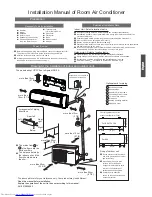
Drawing for the installation of indoor and outdoor units

Necessary Tools for Installation

Hammer

ƽ

Torque wrench

ƽ

(17mm,22mm,26mm)

Nipper

ƽ

Reamer

ƽ

Hacksaw

ƽ

Pipe cutter

ƽ

Gas leakage detector or

ƽ

soap-and-water solution

Hole core drill

ƽ

Flaring tool

ƽ

Spanner(17,19 and 26mm)

ƽ

Knife

ƽ

Measuring tape

ƽ

ƽ

ƽ

ƽ

ƽ

ƽ

Place where the distance of more than lm from televisions, radios, wireless apparatuses
and fluorescent lamps can be left.

ƽ

In the case of fixing the remote controller on a wall, place where the indoor unit can
receive signals when the fluorescent

ƽ

lamps in the room are in use.

ƽ

ƽ

ƽ

A distance marked

ƽ

Q

is available as illustrated in the below figure.

Before inserting power plug into receptacle, check the voltage without fail.
The power source is the same as the

ƽ

corresponding name plate.

Install an exclusive branch circuit of the power.

ƽ

A receptacle shall be set up in a distance where the power cable can be
reached. Do not extend the cable by cutting it.

ƽ

Selection of Installation Place

Power Source

Preparation

NO.00105

36242

Installation Manual of Room Air Conditioner

F

A

C

E

D

Optional parts for piping

Non-adhesive tape

Adhesive tape

Saddle (L.S) with screws

Connecting electric cable

for indoor and outdoor

Drain hose

Heating insulating material

Piping hole cover

Floor fixing dimensions of the

outdoor unit

Fixing of outdoor unit

Fix the unit to concrete or block

ƽ

with bolts (10mm) and nuts firmly

and horizontally.

When fitting the unit to wall

ƽ

surface, roof or rooftop, fix

a supporter securely with nails

or wires in consideration  of 

earthquake and strong wind.

If vibration may affect the

ƽ

house, fix the unit by attaching a 

vibration-proof mat.

The marks from

to

in the figure are the

parts numbers.
The distance between
the indoor unit and the
floor should be more
than 2m.

The models adopt HC FC free refrigerant R410A

more than

10cm (3 7/8)

more than 10cm

(3 7/8)

more than 10cm

(3 7/8)

more than 20cm

(7 7/8)

more than 15cm

(5 7/8)

more than 25cm

(9 7/8)

more than 60cm

(23 5/8)

A

G

ƽ

ƽ

A

F

C

E

D

G

B

Arrangement of piping
directions

Rear left

Left

Rear
right

Right

Below

G

Attention must be paid to
the pitch of drain hose

The above picture is for your reference only. Your product may look different.

Read this manual before installation.
Explain the operation of the unit to the user according to this manual.

Indoor Unit - Select a location that is

Outdoor Unit - Select a location that is

Robust not causing vibration, where the body can be supported sufficiently.

Not affected by heat or steam generated in the vicinity, where inlet and outlet of the 
unit are not disturbed.
Possible to drain easily, where piping can be connected with the outdoor unit.

Where cold air can be spread in a room evenly.

Nearby a power receptacle. (Refer to drawings).

Less affected by rain or direct sunlight and is sufficiently ventilated.
Strong enough to bear the unit, where vibration and noise are not increased.

(4 1/2)

For:24k

Not causing a nuisance to neighbors due to discharged air or noise. 

(10 1/16)

(5 1/2)

(19 2/3)

(5 1/2)

(24 7/8)

(4 1/2)

(13 1/2)

140

500

140

256

113.5

113.5

633

340

For:09k 12k 18k

 (Unit:mm / inch)

Summary of Contents for Room Air Conditioner

Page 1: ...n fitting the unit to wall ƽ surface roof or rooftop fix a supporter securely with nails or wires in consideration of earthquake and strong wind If vibration may affect the ƽ house fix the unit by attaching a vibration proof mat The marks from to in the figure are the parts numbers The distance between the indoor unit and the floor should be more than 2m The models adopt HCFC free refrigerant R410A mor...

Page 2: ...ld up ƽ the body at a slant from the underside and then put it down perpendicularly Connecting the indoor outdoor Electric Cable Removing the wiring cover Remove terminal cover at right bottom corner of indoor unit then take ƽ off wiring cover by removing its screws 1 Insert from outside the room cable into left side of the wall hole in which the pipe has already existed 2 Pull out the cable on th...

Page 3: ... and 2 operate vacuum pump If the low 3 After the completion of vacuuming close the handle Lo in gaugemanifold and stop the operation of the vacuum pump Attaching Drain Elbow Purging Method To use vacuum pump Open the valve rod stem the 2 way valve counterclockwise to 90 degrees 4 After 6 seconds close the 2 way valve and inspect for gas leakage Power cable HSU12VHJ DB W Outdoor unit 3 2 Power Wir...

Page 4: ... Please don t do the drainage as shown below ƽ ƽ Please pour water in the drain pan of the indoor unit and ƽ is carried out surely to outdoor In case that the attached drain hose is in a room please ƽ apply heat insulation to Less than 5cm confirm that drainage it without fail 4 Check Items for Test Run Put check mark in boxes Gas leak from pipe connecting Heat insulation of Are the connecting wiri...

Page 5: ... generado por la unidad no cause una molestia a los vecinos Coloque la unidad en un lugar en el que pueda disponerse de la distancia de separación marcada en la figura anterior Herramientas necesarias para realizar la instalación Fuente de alimentación Selección del lugar de instalación diagrama de instalación de unidades interiores y exteriores Los modelos cumplen la norma R410A sobre refrigerante...

Page 6: ...per los tubos al doblarlos Conecte previamente el cable eléctrico de interior exterior y tire de la conexión al aislante de calor del componente de conexión Conexión de los cables eléctricos de interior exterior Accesorios Selección de tubo Al fijar por primera vez la placa de montaje Orificio de pared Ø70mm Cara interior Grosor de la pared Cara exterior Manguera de drenaje Fijación de la unidad int...

Page 7: ...realizada por un ingeniero profesional en aire acondicionado Antes de añadir refrigerante adicional realice una purga de aire desde los tubos refrigerantes y la unidad interior utilizando una bomba de vacío y cargue después el refrigerante adicional PRECAUCIÓN Unidad interior Unidad exterior Filtro de aceite Unidad exterior Elevación máx Amáx 10m En caso de que la elevación A sea superior a 5m el ...

Page 8: ...invernadero regulados por el Protocolo de Kioto B Carga de refrigerante que contiene el producto de fábrica consulte la placa de características de la unidad C Cantidad de refrigerante adicional cargada durante la instalación D Carga total de refrigerante E Unidad exterior F Botella de refrigerante y colector de carga Prueba de instalación y ejecución de la prueba Explique al cliente cómo utilizar...

Page 9: ... un emplacement où le vent et le bruit ne risquent pas de gêner les voisins Choisir un endroit dans lequel les distances marquées illustrées dans le schéma ci dessus sont disponibles Outillage requis pour l installation Source d alimentation Sélection de l emplacement pour l installation schéma d installation des unités intérieures et extérieures Les modèles utilisent le réfrigérant R410A sans HCF...

Page 10: ... et cintrez ensuite le tuyau selon la position du trou dans le mur Lors du cintrage prenez soin de ne pas écraser les tuyaux Connectez au préalable le câble des unités intérieures extérieures et recouvrez ensuite les câbles connectés avec l isolation Connexion du câble des unités intérieures extérieures Accessoires Sélection du tuyau Lorsque la plaque de fixation est installée pour la 1e fois Trou ...

Page 11: ...outefois la charge de réfrigérant doit être exécuté par un professionnel de la climatisation Avant d ajouter du réfrigérant purgez l air des tuyaux de réfrigération et de l unité intérieure avec pompe à vide Chargez AVERTISSEMENT Unité intérieure Unité extérieure Piège dl huile Unité extérieure Hauteur max Amax 10m Si la hauteur A dépasse les 5m installez un piège à huile tous les 5 à 7 m Longueur...

Page 12: ... unité voir sur la plaque signalétique de l unité C Quantité supplémentaire de réfrigérant chargée sur place D Charge totale de réfrigérant E Unité extérieure F Cylindre réfrigérant et collecteur de chargement Vérification de l installation et test de fonctionnement Expliquez le fonctionnement à vos clients en vous servant du manuel Cochez les cases Fuite de gaz dans le raccordement du tuyau Isolat...

Reviews: