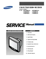
Haier HTAR14, Service Manual
The Haier HTAR14 Service Manual is now available for free download on our website. This comprehensive manual provides detailed instructions on operating and maintaining your Haier HTAR14, ensuring optimal performance. Download it now from manualshive.com to access this valuable resource and enhance your user experience.
Share
Download


Reviews:
No comments
Related manuals for HTAR14
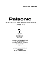
3410
Brand: Palsonic Pages: 21
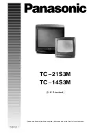
TC-14S3M
Brand: Panasonic Pages: 4
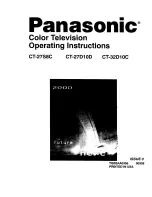
CT-27D10D
Brand: Panasonic Pages: 21
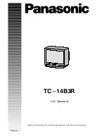
TC-14B3R
Brand: Panasonic Pages: 16

CT-27G23
Brand: Panasonic Pages: 32
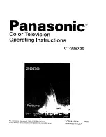
CT-32SX30
Brand: Panasonic Pages: 27
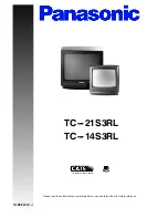
TC-14S3RL
Brand: Panasonic Pages: 16
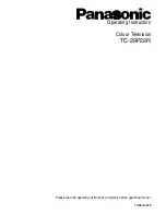
Viera TC-29P22R
Brand: Panasonic Pages: 31
TX-W36D3DP
Brand: Panasonic Pages: 37
TXK 3276
Brand: Samsung Pages: 72
CS29A200
Brand: Samsung Pages: 44
CW-29M026P
Brand: Samsung Pages: 48
HC-P5256W
Brand: Samsung Pages: 2
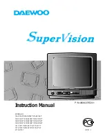
Super Vision 14A5
Brand: Daewoo Pages: 13
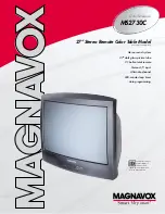
MS2730C - 27i Color Tv
Brand: Magnavox Pages: 2
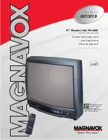
MT1301B
Brand: Magnavox Pages: 2
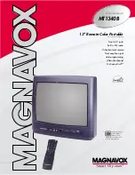
MT1340B
Brand: Magnavox Pages: 2
3498
Brand: Palsonic Pages: 13


