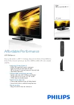
background image

Order No.

LED LCD TV

Model No.

Chassis

This service information is designed for experienced repair technicians only and is not designed for use by the general public. 

It does not contain warnings or cautions to advise non-technical individuals of potential dangers in attempting to service a product.

Products powered by electricity should be serviced or repaired only by experienced professional technicians. Any attempt to service or repair 

the product or products dealt with in this service information by anyone else could result in serious injury or death.

Haier Group

©2010  Qingdao Haier Electronics Co., Ltd.

All rights reserved. Unauthorized copying and distribution is a violation of law.

SERVICE MANUAL

WARNING

Service mode.

TV1003S016V0

MTK5305

HL32XSL2a/HL32XSLW2a

HL32XSL2/HL32XSLW2


Summary of Contents for HL32XSL2

Page 1: ...roduct Products powered by electricity should be serviced or repaired only by experienced professional technicians Any attempt to service or repair the product or products dealt with in this service information by anyone else could result in serious injury or death Haier Group 2010 Qingdao Haier Electronics Co Ltd All rights reserved Unauthorized copying and distribution is a violation of law SERV...

Page 2: ...sed in this manual 6 1 4 How to Read this Service Manual 7 1 4 1 Using icons 7 Chapter 2 Specification 2 1 Specification list 8 2 2 External pictures four faces 9 Chapter 3 Disassemble and Assemble 3 1 Remove the Stand 10 3 2 Remove the Power Cord 11 3 3 Remove the Back Cover 11 3 4 Remove the Mainboard 11 3 5 Remove the speaker 11 3 6 Remove the Keypad 12 3 7 Remove the Remote Control Board 12 3 ...

Page 3: ... panel Controls 24 6 3 Get to know your remote control 25 Chapter 7 Electrical Parts 7 1 Block Diagram 26 7 2 Circuit Diagram 27 7 3 Wiring Connection Diagram 45 Chapter 8 Measurements and Adjustments 8 1 Service Mode 46 8 1 1 How to enter into Service Mode 46 8 1 2 How to exit 46 8 2 Measurements and Adjustments 46 8 2 1 The Main Menu 46 8 2 2 Video 47 8 2 3 Audio 48 8 2 4 Software UpDate 48 Chap...

Page 4: ...r the service personnel to open the units and disassemble the units For example we need to describe properly how to avoid the possibility to get electrical shock from the live power supply or charged electrical parts even the power is off This symbol indicates that high voltage is present inside It is dangerous to make any kind of contact with any inside part of this product This symbol indicates ...

Page 5: ...embly on a conductive surface such as aluminum foil to prevent electrostatic charge buildup or exposure of the assembly 1 3 4 About lead free solder PbF This product is manufactured using lead free solder as a part of a movement within the consumer products industry at large to be environmentally responsible Lead free solder must be used in the servicing and repairing of this product 1 3 5 Use the...

Page 6: ...se in this service manual lubrication of contacts is not required Capacitors may result in an explosion hazard 5 Do not defeat any plug socket B voltage interlocks with which receivers covered by this service manual might be equipped 6 Do not apply AC power to this instrument and or any of its electrical assemblies unless all solid state device heat sinks are correctly installed 7 Always connect t...

Page 7: ...will be installed CAUTION Be sure no power is applied to the chassis or circuit and observe all other safety precautions 17 Minimize bodily motions when handling unpackaged replacement ES devices Otherwise harmless motion such as the brushing together of your clothes fabric or the lifting of your foot from a carpeted floor can generate static electricity sufficient to damage an ES device 1 3 7 Ord...

Page 8: ...e but may nevertheless be valuable to the reader such as tips and tricks Caution A caution is used when there is danger that the reader through incorrect manipulation may damage equipment loose data get an unexpected result or has to restart part of a procedure Warning A warning is used when there is danger of personal injury Reference A reference guides the reader to other places in this binder o...

Page 9: ...gel of view 178 Contrast 4000 1 Brightness 450cd m2 OSD language English etc Color system ATSC NTSC Audio system BG DK I L Audio output power Built in W 9W 2 Audio output power outer W No Total power input W 160W Voltage range V 90 240V Power frequency Hz 50 60HZ Net weight KG 18 4 Gross weight KG 26 Net dimension MM 1122 31 706 Packaged dimension MM 1255 245 830 LEA32T3 ...

Page 10: ...Service Manual Model No HL32XSL2 9 2 2 External pictures four faces Front Side Left Side ...

Page 11: ...1 Remove the Stand 1 Lay down the unit so that back cover faces upward 2 Remove the Five screws from the back cover which are indicated with the circles in the picture above 3 Remove the stand Service Manual Model No HL32XSL2 10 Back Side ...

Page 12: ...wer Cord Then remove the power cord Remove the screw indicated by the red circles in below picture Then remove the mainboard 3 4 Remove the Mainboard Remove the five screws indicated by the red circles in below picture 3 5 Remove the speaker Remove the screw indicated by the red circles in below picture Then remove the speaker Service Manual Model No HL32XSL2 11 ...

Page 13: ...he remote control board 3 7 Remove the Remote Control Board 3 9 Remove the indicator light The indicator light is buckled into the front frame remove the clasp indicated by the red circles in below picture Take out the indicator light 3 8 Remove the Stand backstop Remove the six screws indicated by the red circles in below picture Take out the stand backstop Service Manual Model No HL32XSL2 12 ...

Page 14: ...1 Board Location No Parts number Description A Board 0094001821DA PANEL B Board 0094001839 Power Board C Board Mainboard 0090724519 4 2 Main Board Service Manual Model No HL32XSL2 13 A B C CND4 CND3 CON2 CNE2 CNA1 CND5 CNE1 DC1BA0E0200M DC1BA0E0100M ...

Page 15: ... ROUT 12V 5V Connector CNA1 Keypad Connector CNE2 Pin number Signal name 1 12V 2 12V 3 GND 4 12V 5 GND 6 GND 7 5VSTB 8 9 GND 10 PW ON OFF 11 PB ADJUS 12 PB ON OFF Pin number Signal name 1 GND 2 KEY1 3 KEY0 4 3 3VS Rom connector CNE1 Pin number Signal name 1 5VS 2 IR 3 LED R 4 LED G 5 GND 4 3 Power Supply Board 4 3 1 Function description To supply power for Mainboard Panel 4 3 2 Connector definitio...

Page 16: ...4 4 LCD Panel Service Manual Model No HL32XSL2 15 CNM801 ...

Page 17: ...1 st 5 th LVDS Signal 11 Rx1 0 P 1 st 5 th LVDS Signal 12 Rx1 1 N 1 st 5 th LVDS Signal 13 Rx1 1 P 1 st 5 th LVDS Signal 14 Rx1 2 N 1 st 5 th LVDS Signal 15 Rx1 2 P 1 st 5 th LVDS Signal 16 GND Ground 17 Rx1CLK 1 st 5 th LVDS Clock 18 Rx1CLK 1 st 5 th LVDS Clock 19 GND Ground 20 Rx1 3 N 1 st 5 th LVDS Signal 21 Rx1 3 P 1 st 5 th LVDS Signal 22 Rx1 4 N 1 st 5 th LVDS Signal 23 Rx1 4 P 1 st 5 th LVD...

Page 18: ...nal 29 Rx3 2 N 3 rd 7 th LVDS Signal 30 Rx3 2 P 3 rd 7 th LVDS Signal 31 GND Ground 32 Rx3CLK 3 rd 7 th LVDS Clock 33 Rx3CLK 3 rd 7 th LVDS Clock 34 GND Ground 35 Rx3 3 N 3 rd 7 th LVDS Signal 36 Rx3 3 P 3 rd 7 th LVDS Signal 37 Rx3 4 N 3 rd 7 th LVDS Signal 38 Rx3 4 P 3 rd 7 th LVDS Signal 39 GND Ground 40 NC NC 41 NC NC Service Manual Model No HL32XSL2 17 ...

Page 19: ...l 13 Rx2 1 P 2 nd 6 th LVDS Signal 14 Rx2 2 N 2 nd 6 th LVDS Signal 15 Rx2 2 P 2 nd 6 th LVDS Signal 16 GND Ground 17 Rx2CLK 2 nd 6 th LVDS Clock 18 Rx2CLK 2 nd 6 th LVDS Clock 19 GND Ground 20 Rx2 3 N 2 nd 6 th LVDS Signal 21 Rx2 3 P 2 nd 6 th LVDS Signal 22 Rx2 4 N 2 nd 6 th LVDS Signal 23 Rx2 4 P 2 nd 6 th LVDS Signal 24 GND Ground 25 Rx4 0 N 4 th 8 th LVDS Signal 26 Rx4 0 P 4 th 8 th LVDS Sign...

Page 20: ...K 4 th 8 th LVDS Clock 34 GND Ground 35 Rx4 3 N 4 th 8 th LVDS Signal 36 Rx4 3 P 4 th 8 th LVDS Signal 37 Rx4 4 N 4 th 8 th LVDS Signal 38 Rx4 4 P 4 th 8 th LVDS Signal 39 GND Ground 40 NC NC 41 NC NC 42 NC NC 43 NC NC 44 NC NC 45 LVDS_SEL HIGH 3 3V Normal LVDS Format LOW GND JEIDA LVDS Format 46 NC NC 47 NC NC 48 NC NC 49 NC NC 50 NC NC 51 NC NC Service Manual Model No HL32XSL2 19 ...

Page 21: ...ntenna Connection Connect one end of a coaxial cable not included to the ANT IN jack on the back of your TV DVD combo then connect the other end of the cable into the antenna or cable TV wall outlet 7R LPSURYH SLFWXUH TXDOLW IURP DQ DQWHQQD LQ D SRRU VLJQDO DUHD LQVWDOO D VLJQDO DPSOL HU Service Manual Model No HL32XSL2 20 ...

Page 22: ...st for you VCR connection Connecting a VCR with a standard AV cable A standard AV connection provides good video and audio To connect a VCR with a standard AV cable 1 Make sure that your TV DVD combo and the VCR are turned off 2 Connect a standard AV cable not included to the VIDEO IN yellow and adjust R red and L white AUDIO jacks on the back of your TV DVD combo then connect the other end of the...

Page 23: ...hen press ENTER External Equipment Connections Connecting a component video device A component video device provides better video than an S Video connection To connect a component video device 1 Make sure that your TV DVD combo and the component video device are turned off 2 Connect a component video cable not included to the Pr Pb and V jades on the back of your TV DVD combo then connect the othe...

Page 24: ...Chapter 6 Operation Instructions 6 1 Front Panel Controls Service Manual Model No HL32XSL2 23 ...

Page 25: ...Service Manual Model No HL32XSL2 24 6 2 Back Panel Controls ...

Page 26: ...nt modes TV VCR CABLE DVD SETBOX or AUDIO Pressing the corresponding button on the remote control allows you to switch between these modes DQG FRQWURO ZKLFKHYHU SLHFH RI HTXLSPHQW RX FKRRVH Note The remote control might not be compatible with all DVD Players VCRs and Cable boxes Service Manual Model No HL32XSL2 25 ...

Page 27: ...Chapter 7 Electrical Parts 7 1 Block Diagram Service Manual Model No LEA32T3 26 ...

Page 28: ...DIN0 OPCTRL0 OPCTRL1 OPCTRL2 OPCTRL3 ADIN1 ADIN2 ADIN1 ADIN2 ADIN3 ADIN4 ADIN5 strap 0 HDMI_Switch_CTRL0 jtdi I strap 1 OPWM0 OPWM1 OPWM2 OPWM0 OPWM1 OPWM2 TP_VPLL TP_VPLL AMP Set H HPD2_HDMI HPD_sink HPD_SINK OPWRSB ASPDIF ASPDIF OPWRSB Power Module ON OFF LO POWER_ON strap 2 LVDS_PWR_ON U1RX U1TX LVDS_PWR_ON LVDS_PWR_ON HI LVDS POWER ON OPWR1_5V 24C32 WP L Write Enable OPWR2_5V AMP MUTE Hi MUTE ...

Page 29: ...awn MT5305A P1V1 V1 C 2 15 Friday December 04 2009 Placement SYS Flow MediaTek Confidential By Ray DELETE S_VIDEO AIN0 Audio Mapping AV1 VGA DVI 2 1 AV2 YPBPR 1 I2S PWM AR L0 PWM AR L1 R L Line out MT5305A Tuner MPX IF ADC_IN R L x 4 LM4558 LM4558 Speaker HeadPhone TDA1308 NC I2S PWM AR L0 PWM AR L1 MT5305A R L Line out Tuner MPX IF ADC_IN R L x 5 LM4558 AV1 LM4558 For 19 22 24 model 4 AUDIO IN Au...

Page 30: ...7uF 16v NC ACE641 47uF 16v NC AC993 1uF AC993 1uF C26 0 1uF C26 0 1uF AR264 5 1K_1 R0603 SMD AR264 5 1K_1 R0603 SMD ACB442 0 1uF ACB442 0 1uF AFB87 80 R 100mHz AFB87 80 R 100mHz AR268 27K_1 R0603 SMD AR268 27K_1 R0603 SMD ACB623 0 1uF ACB623 0 1uF ACE637 220uF 16v NC ACE637 220uF 16v NC AU61 AX1212 AP1122 AU61 AX1212 AP1122 GND 1 OUT 2 IN 3 AC222 0 1uF AC222 0 1uF AR265 2 2K AR265 2 2K ACB626 0 1u...

Page 31: ...SPC4 1uF SPC4 1uF C6 10nF C6 10nF SPC9 1uF SPC9 1uF R88 100K R88 100K SPC21 NS 1uF SPC21 NS 1uF C15 0 1uF C15 0 1uF SPC3 47uF 16v SPC3 47uF 16v SPR3 180_1 R0603 SMD SPR3 180_1 R0603 SMD L5 10uH 3A L5 10uH 3A 1 2 SPC10 0 1uF SPC10 0 1uF C22 0 1uF C22 0 1uF SPU4 AX1117EJ adj SPU4 AX1117EJ adj GND 1 OUT 2 IN 3 SPC2 NS 0 1uF SPC2 NS 0 1uF SPU1 G1117 adj SPU1 G1117 adj ADJ GND 1 OUT 2 IN 3 SPU3 AP1084 ...

Page 32: ...VSS K8 DVSS K9 DVSS L10 DVSS L11 DVSS L12 DVSS L3 DVSS L9 DVSS M10 DVSS M11 DVSS M13 DVSS M8 DVSS N11 DVSS N12 DVSS N3 DVSS N9 DVSS T12 DVSS U5 DVSS V5 VCCK A18 VCCK A19 VCCK A20 VCCK B17 VCCK B18 VCCK C16 VCCK C17 VCC3IO_3 C18 VCCK D15 VCCK D16 VCCK E14 VCCK E15 VCCK H10 VCCK H12 VCCK J11 VCCK J13 VCCK J9 VCCK L13 VCCK L8 VCCK M12 VCCK M9 VCCK N10 VCCK N13 VCCK N8 VCC3IO_1 R5 VCC3IO_1 T4 VCC3IO_2...

Page 33: ...DDRV 5 AV125 3 5 8 9 12 ADIN5 9 OPWM2 6 ADIN4 14 AVDD33_HDMI 8 AOLRCK AOBCK AOMCLK AOSDATA0 ADIN1 6 ADIN0 6 AIN0_L AIN0_R CVBS0P 9 OPWR0_5V 8 HPD_SINK 8 LVDS_CTRL2 Title Size Document Number Rev Date Sheet of MediaTek Inc TEL 03 567 0766 FAX 03 578 7610 No 1 2 Innovation Rd 1 SBIP Hsin Chu City 300 Drawn MT5305A P1V1 V1 C 4 15 Thursday December 03 2009 MT5305A MediaTek Confidential Title Size Docu...

Page 34: ...3 1 5nF_X7R_50V ACD128 0 1uF ACD128 0 1uF ACD157 10uF 10V ACD157 10uF 10V CD33 4 7uF 10V CD33 4 7uF 10V ACD137 1 5nF_X7R_50V ACD137 1 5nF_X7R_50V ARD6356 ARD6356 ACD126 0 1uF ACD126 0 1uF ACD115 4 7nF ACD115 4 7nF ACD140 0 1uF ACD140 0 1uF ARD58 300 ARD58 300 ARD4722 ARD4722 ACD142 NS 0 1uF ACD142 NS 0 1uF ACD147 4 7nF ACD147 4 7nF ARD6256 ARD6256 ACD134 330pF_C0G_50V ACD134 330pF_C0G_50V ARD6156 ...

Page 35: ...15 0 1uF CD15 0 1uF CD30 NS 0 1uF CD30 NS 0 1uF RD26 1K_1 RD26 1K_1 RD19 56 RD19 56 CD3 NS 0 1uF CD3 NS 0 1uF CD31 0 1uF CD31 0 1uF CD25 0 1uF CD25 0 1uF CD12 1uF CD12 1uF CD32 4 7uF 10V CD32 4 7uF 10V RD18 1K_1 RD18 1K_1 CM22 0 1uF CM22 0 1uF CD14 0 1uF CD14 0 1uF CD24 0 1uF CD24 0 1uF CD1 0 1uF CD1 0 1uF RND7 56 RND7 56 1 2 3 4 5 6 7 8 CD29 0 1uF CD29 0 1uF CM21 0 1uF CM21 0 1uF RD14 22 RD14 22 ...

Page 36: ...03 BR33 4 7K NC R0402 SMD BR33 4 7K NC R0402 SMD AC1026 0 1uF C0402 SMD A AC1026 0 1uF C0402 SMD A ATP14 TP SMD D0 6 ATP14 TP SMD D0 6 AFB81 0603_Bead BEAD SMD 0603 AFB81 0603_Bead BEAD SMD 0603 BR38 4 7K NC R0402 SMD BR38 4 7K NC R0402 SMD AFB80 0603_Bead BEAD SMD 0603 AFB80 0603_Bead BEAD SMD 0603 ATP30 TP SMD D0 6 ATP30 TP SMD D0 6 BR46 0R NC R0402 SMD BR46 0R NC R0402 SMD BR34 4 7K R0402 SMD B...

Page 37: ...I NORMAL NEAR IC 20090612 Modify 09 06 19 KEY PANEL HI LED RED LO LED GREEN FOR DEBUGGING RESEVED FOR EXTEND FUNCTION Layout anywhere TP25 TP25 PR1 33 PR1 33 Q63 2N3904 Q63 2N3904 1 3 2 R1774 100 R1774 100 CNA2 USB CON CNA2 USB CON __VBUS 1 __D 2 __D 3 __GND 4 GND 5 GND 6 R1770 15K R1770 15K CNB2 PH3 4A NC CNB2 PH3 4A NC 1 2 3 4 D2 ESD_0402_10pF D2 ESD_0402_10pF 1 2 YU1 EEPROM 24C32 W YU1 EEPROM 2...

Page 38: ... SBIP Hsin Chu City 300 Drawn MT5305A P1V1 V1 C 7 15 Friday November 27 2009 FLASH TRAP BYPASS FCI MediaTek Confidential Title Size Document Number Rev Date Sheet of MediaTek Inc TEL 03 567 0766 FAX 03 578 7610 No 1 2 Innovation Rd 1 SBIP Hsin Chu City 300 Drawn MT5305A P1V1 V1 C 7 15 Friday November 27 2009 FLASH TRAP BYPASS FCI MediaTek Confidential By Ray Serial Flash Dual Layout 8MB default XT...

Page 39: ...42 1 2 D101 RB520S 30 NC D101 RB520S 30 NC 2 1 D15 D15 1 2 D99 D99 1 2 D90 ESD_0402_10pF D90 ESD_0402_10pF 1 2 D50 ESD_0402_10pF D50 ESD_0402_10pF 1 2 HR35 0 HR35 0 R14 33K R14 33K D64 ESD_0402_0 15pF D64 ESD_0402_0 15pF 1 2 D100 D100 1 2 D117 ESD_0402_10pF D117 ESD_0402_10pF 1 2 CN10 HDMI_con CN10 HDMI_con SHELL1 20 SHELL2 21 D2 1 D2 Shield 2 D2 3 D1 4 D1 Shield 5 D1 6 D0 7 D0 Shield 8 D0 9 CK 10...

Page 40: ...nF VC2 10nF QF6 2N7002 QF6 2N7002 1 3 2 VR18 10K VR18 10K VR4 0 VR4 0 OC18 560pF OC18 560pF VR22 47K VR22 47K VC4 10nF VC4 10nF GC8 2 2uF GC8 2 2uF BC18 15pF BC18 15pF VR26 10K VR26 10K GR4 0 GR4 0 GR5 100 GR5 100 D58 ESD_0402_10pF D58 ESD_0402_10pF 1 2 D71 ESD_0402_10pF D71 ESD_0402_10pF 1 2 VR12 0 VR12 0 VR9 10K VR9 10K OC14 560pF OC14 560pF OC19 560pF OC19 560pF BC15 15pF BC15 15pF VR19 10K VR1...

Page 41: ...4558 3 2 1 8 4 STR21 75 STR21 75 CE629 22uF 16v CE629 22uF 16v R1781 4 7K R1781 4 7K C647 1000pF C647 1000pF L147 FB L147 FB EC2 100pF NC EC2 100pF NC Q60 2N3904 Q60 2N3904 1 3 2 R1730 10K R1730 10K EC16 220uF 16v EC16 220uF 16v CE642 22uF 16v CE642 22uF 16v C645 100pF C645 100pF C11 10uF 16v C11 10uF 16v R1799 10K R1799 10K EC14 NS 470pF EC14 NS 470pF C749 0 1uF C749 0 1uF R1762 0 15K R1762 0 15K...

Page 42: ... 4 7K 470 R1817 4 7K 470 R1823 33 R1823 33 C770 10uF 10V C770 10uF 10V R1812 100K R1812 100K L148 33uH 2A L148 33uH 2A 1 2 XQ7 2N3904 XQ7 2N3904 1 3 2 CE647 47uF 16V CE647 47uF 16V H2 HOLE GND H2 HOLE GND 2 2 3 3 4 4 5 5 9 9 8 8 7 7 6 6 1 1 C772 0 22uF 25V C772 0 22uF 25V R1831 10K R1831 10K R1815 0 R1815 0 R1833 10K R1833 10K C766 0 047uF 25V C766 0 047uF 25V C789 100uF 35V C789 100uF 35V C790 10...

Page 43: ...7610 No 1 2 Innovation Rd 1 SBIP Hsin Chu City 300 Drawn MT5305A P1V1 V1 C 12 15 Friday December 04 2009 LVDS BACKLIGHT MediaTek Confidential Title Size Document Number Rev Date Sheet of MediaTek Inc TEL 03 567 0766 FAX 03 578 7610 No 1 2 Innovation Rd 1 SBIP Hsin Chu City 300 Drawn MT5305A P1V1 V1 C 12 15 Friday December 04 2009 LVDS BACKLIGHT MediaTek Confidential By Ray NEAR IC NEAR IC HI LVDS ...

Page 44: ...NEAR IC NEAR IC TUNER POWER 5V_TUNER Near Tuner Near Tuner Near IC 20090612 20090612 POWER SUPPLY 5V FOR TUNER muRata LQM18NNR22K00 和 LQM18NNR39K00 Near Tuner Near MT538X Use muRata Inductor and TDK Capacitor ZR15 0 ZR15 0 ZR3 4 7K ZR3 4 7K C1 NC C1 NC C802 100pF NC C802 100pF NC ZFB14 NC 0603 ZFB14 NC 0603 ZFB13 NC 0603 ZFB13 NC 0603 L152 220nH L152 220nH ZFB15 0 ZFB15 0 ZR10 100 ZR10 100 ZFB8 NC...

Page 45: ...i DVD PowerOff R8 2 2K R8 2 2K CE2 220uF 16V CE2 220uF 16V C20 0 1uF C20 0 1uF Q4 2N3904 Q4 2N3904 1 3 2 C13 0 1uF C13 0 1uF XQ2 2N3904 XQ2 2N3904 1 3 2 T6 T6 L3 10uH 3A L5_9 L3 10uH 3A L5_9 1 2 Q3 2N3904 Q3 2N3904 1 3 2 CPR14 0 R1206 SMD CPR14 0 R1206 SMD L4 10uH 3A L5_9 L4 10uH 3A L5_9 1 2 T4 T4 R89 100K R89 100K R9 2 7K_1 R0603 SMD R9 2 7K_1 R0603 SMD C14 0 1uF C14 0 1uF C5 10nF C5 10nF CPC30 1...

Page 46: ...55 10K BC3 1 5nF BC3 1 5nF CE654 10uF 10V CE654 10uF 10V BR6 56 BR6 56 CN14 DVD_LR_IN CN14 DVD_LR_IN 1 2 3 BR17 75 BR17 75 BD5 ESD_0402_10pF BD5 ESD_0402_10pF 1 2 BD4 ESD_0402_10pF BD4 ESD_0402_10pF 1 2 OC25 560pF OC25 560pF BR15 18 BR15 18 SC2 47pF SC2 47pF BD3 ESD_0402_10pF BD3 ESD_0402_10pF 1 2 C673 10uF 10v C673 10uF 10v BR42 75 BR42 75 BR10 68 BR10 68 T9 T9 BR8 100 BR8 100 R1856 10K R1856 10K...

Page 47: ...e Connection Wire 12V 5V Remote Control Board Assembly CN5 CN8 CN4 CN10 CN27 CNB3 CNB4 CNE2 CNE3 JP1 PD801 CNM801 CN2 CN1 Power Cord 0090401964 Connection Wire 12V 5V LVDS Wire LVDS Wire Speaker Wire Connection Wire Control Connection Wire Remote Connection Wire Lamp Connection Wire Lamp 0090401643C 0090402750B 0090402553A 0090402739 0090402724C 0090400647J 0090402846 9 0090401861 Connection Wire ...

Page 48: ... out the factory mode menu 8 2 Measurements and Adjustments 8 2 1 The Main Menu In factory mode menu press up down button to choose the up down item press left right button to the submenu press OK button to affirm press MENU button go to the next page MTK5305 Factory Menu In this page you just consider RESET ALL function This function you can reset all date return to factory state if you encounter...

Page 49: ...8 2 2 Video Color Temperature This page is control the Color Temperature and the picture size Service Manual Model No HL32XSL2 47 ...

Page 50: ... In this page you just consider the software update function Plug USB into the 1st USB port select SOFTWARE UPDATE press OK Then flip the other window perss OK The update is going work NOTE After software update turn to the Factory Setting 1 page reset all Service Manual Model No HL32XSL2 48 ...

Page 51: ...ify if correct channel is selected Adjust the antenna Make adjustments by Fine Tune and MANUAL Scan No color for some channel program black and white Verify if the same problem exists in other channels check out of picture and sound system Refer to relative instructions in the Manual for color adjust Spots with some or all pictures Verify if the antennal is correctly connected Verify if the antenn...

Page 52: ...7nF C160 0 1uF C121 470nF C140 1uF C281 330pF 25V R334 22 C283 100nF 25V CA84 470uF 35V C100 0 1uF C258 100nF 25V R329 100 R306 10K C291 100nF 25V R346 22 C244 100nF 25V R359 12 R494 12 C79 0 1uF L31 600 4 5X3 2 C117 680pF GND_SUB 1 SA 2 TEST_MODE 3 VSS 4 VCC_REG 5 OUT2B 6 GND2 7 VCC2 8 OUT2A 9 OUT1B 10 VCC1 11 GND1 12 OUT1A 13 GND_REG 14 VDD 15 CONFIG 16 OUT3B DDX3B 17 OUT3A DDX3A 18 EAPD OUT4B 1...

Page 53: ...B D Source Re soldering or change IC U13 Check the input output Of IC U55 of Main B D Source Re soldering or change IC U55 Check the input output Of IC U2 of Main B D Source Re soldering or change IC U2 Check the Speaker Change the Speaker Check the Sperker wire Fail Pass Fail Fail Fail Fail Pass Pass Pass Pass Service Manual Model No HL32XSL2 51 ...

Page 54: ...Sunken TCP lead cracking ACF bonding short Awful environment and something electric enter into LCD Mis align between TCP and Panel Panel failure TCP failure V Dim Vertal gray line V L D Vertical color line light or dark forever H B D Horizontal bar H Dim Horizontal gary line H L D Horizontal line light or dark forever Service Manual Model No HL32XSL2 52 ...

Page 55: ...er Bladder between Polarizer and top glass Polarizer Scratch Polarizer Scratch Tine or rigidity arose F inside Polarizer Eyewinker inside Polarizer Eyewinker inside Polarizer Circuit Abnormal Display Abnormal Display 1 Chip lose action 2 IC ahort or jointiog bad 3 Pannel and vsc connect bad Flashing Bright and dark display alternately Service Manual Model No HL32XSL2 53 ...

Page 56: ...nt and EDS Black Screen B L normal only Black screen display FIIcker Crosstalk LCD Vcom imbalance Abnormal Color Only color abormal Capacitance improper bring crosstalk inside LCD pannel Abnormal Color Only color abnormal 1 Chip lose action 2 IC short or jointion bad 3 Pannel and vsc connect bad Service Manual Model No HL32XSL2 54 ...

Page 57: ...wire and electrode B L dark B L brightness darker than normal Connect badnessShort between wire and electrode B L wire damaged B L wire damaged Operation abnormal or systemic noise B L wire open Without backlight Operation abnormal or systemic noise B L shut down B L shutdown in sometime Short bitween lamp housing and wire Because consume power too much F M F M inB L white balck Rotundity or wirel...

Page 58: ...lcal or B L Light leakage Brightness at bottom of LCM brighter than normal B L unit badness Uniformity B L brightness asymmetric Sheet in B L unit is uneven Mount hole Lack screw or screw damage Lack screw Screw damage Service Manual Model No HL32XSL2 56 ...

Page 59: ...Sincere Forever Haier Group Haier Industrial Park No 1 Haier Road 266101 Qingdao China http www haier com Printed in China ...

Reviews: