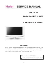
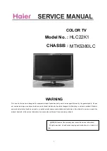
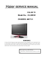
background image


WARNING 

This service information is designed for experienced repair technicians only and is not designed for use by the general public. It does 

not contain warnings or cautions to advise non-technical individuals of potential dangers in attempting to service a product. Products 

powered b electricity should be serviced or repaired only by experienced professional technicians. Any attempt to service or repair the 

product deal with in this service information by anyone else could result in serious injury or death. 
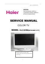


COLOR TV

Model No. : 

H

L22

KN1


CHASSIS:

 MST721


2009 (Qingdao Electronics 

limited company

 All rights reserved. Unauthorized copying and distribution is a violation of 

law. 

Haier

Summary of Contents for HL22KN1

Page 1: ...tempting to service a product Products powered b electricity should be serviced or repaired only by experienced professional technicians Any attempt to service or repair the product deal with in this service information by anyone else could result in serious injury or death COLOR TV Model No HL22KN1 CHASSIS MST721 2009 Qingdao Electronics limited company All rights reserved Unauthorized copying an...

Page 2: ...on 7 3 2 Main Board 8 3 3 Power Board 12 3 4 Lcd Panel 13 4 Disassemble And Assemble 14 5 Installation Instructions 19 6 Operation Instructions 24 6 1 Front Panel Controls 24 6 2 Back Panel Controls 24 6 3 Universal Remote Controller 26 7 Measurements And Adjustments 27 8 Electrical Parts 29 9 Trouble Shooting 40 CONTENT Tableofconents 2 8 1Connetive Wire Photo 29 8 2Circuit Diagram 29 ...

Page 3: ...he literture accompanying the appliance 1 2 2 Be careful to the electrical shock To prevent damage which might result in electric shock or fire do not expose this TV set to rain or excessive moisture This TV must not be exposed to dripping or splashing water and objects Filled with liquid such as vases must not be place on top of or above the TV 1 2 3 Electro static discharge ESD Some semiconducto...

Page 4: ...arts Please include the following informations when you order parts Particularly the Version letter 1 Model number and Version letter The model number can be found on the back of each product and the Version letter can be found at the end of the serial number 2 Part No and Description You can find them in your service manual 1 2 8 Photo used in this manual The illustration and photos used in this ...

Page 5: ...cd m2 Contrast Ratio 800 1 Angel of view H170 V160 Color display 16 7M OSD language English 3D decoder NO 2D comb filter YES DNR YES 3A ENGINE NO Same picture split demo SPD NO double picture demo DPD NO AV stereo YES Surrounding sound NO NICAM YES MUSIC STANDARD THEATRE USE MUSIC THEATRE PERSONAL VOICE Bass Treble YES Balance YES BBE NO LIP SYNC NO Equalizer NO Earphone YES Mute YES AV input NO D...

Page 6: ...mode YES ADVANCED 4 3 YES PIP NO POP NO PBP NO 3A WINDOWS NO ATS YES Nation Select YES Channel List NO Input Frequency by Manual and Channel Number Input NO Lock YES TELTEXT 10 NO of built in speakers 2 NO of outer speakers No Color display 240 NO of preset channels 100 OSD language English Color system PAL SECAM Audio system DK BG I LL Audio output power Built in W 1 5W 2 ...

Page 7: ... 60W Voltage range V AC150V AC240V Power frequency Hz 50 60Hz Time of sleep timer MINS 240Min Net weight KG 5 38 Gross weight KG 6 73 Net dimension MM 537 189 454 Packaged dimension MM 595 225 460 3 LOCATION OF CONTROLS AND COMPONENTS 3 1 Board Location ...

Page 8: ...8 No Parts number Description A Board MainBoard Assembly B Board Power adaptor C Speaker 3 2 A Board MainBoard 3 2 1 Function Description Main Board ...

Page 9: ...te into signal that panel can display 3 2 2 Connector definition Main board connector LCDS Connector CN2 Pin number Signal name Description 1 LCD VDD Supply voltage to Panel 2 LCD VDD Supply voltage to Panel 3 LCD VDD Supply voltage to Panel 4 GND Ground 5 GND Ground ...

Page 10: ...VDS ODD Clock Signal 16 RXOC LVDS ODD Clock Signal 17 RXO3 LVDS ODD 3 Signal 18 RXO3 LVDS ODD 3 Signal 19 RXE0 LVDS EVEN 0 Signal 20 RXE0 LVDS EVEN 0 Signal 21 RXE1 LVDS EVEN 1 Signal 22 RXE1 LVDS EVEN 1 Signal 23 RXE2 LVDS EVEN 2 Signal 24 RXE2 LVDS EVEN 2 Signal 25 GND Ground 26 GND Ground 27 RXEC LVDS EVEN Clock Signal 28 RXEC LVDS EVEN Clock Signal 29 RXE3 LVDS EVEN 3 Signal 30 RXE3 LVDS EVEN ...

Page 11: ...R Switch Control 6 12V 12V Power 7 12V 12V Power Audio Output Connector CN11 Pin number Signal name Description 1 LSPK Left Audio Output 2 GND Ground 3 GND Ground 4 RSPK Right Audio Output Remote Board and Key board Connector CN15 Pin number Signal name Description 1 IR_IN IR 2 CPU5V 5V Power 3 LED_G Green Indicator light 4 GND Ground 5 LED_R Red Indicator light 6 K6 Key Connector POWER ...

Page 12: ...y Connector V 12 K0 Key Connector SOURCE 3 3B Board Power Board Supply power for Main board and Panel Power supply and Inverter Connector CN6 Pin number Signal name Description 1 ON OFF Preparative switch control 2 GND Ground 3 GND Ground 4 ADJ INVERTER Lightness Adjust 5 BLON INVERTER Switch Control ...

Page 13: ...13 6 12V 12V Power 7 12V 12V Power AC150V AC240V Input CN6 Power supply for panel CN2 CN3 CN4 CN5 3 4 LCD PANEL ...

Page 14: ...14 4 DISASSEMBLE AND ASSEMBLE ...

Page 15: ...15 HL22KN1 KNOCKED DOWN SHOW ...

Page 16: ...16 ...

Page 17: ...17 ...

Page 18: ...18 ...

Page 19: ...19 5 INSTALLATION INSTRUCTIONS Accessories Remote Control User Manual Battery Audio wire ...

Page 20: ...20 ...

Page 21: ...21 ...

Page 22: ...22 ...

Page 23: ...23 ...

Page 24: ...24 6 OPERATION INSTRUCTIONS Basal information 6 1 Front panel controls 6 2 Back panel controls ...

Page 25: ...25 ...

Page 26: ...26 6 3 Setting up Your Remote Control ...

Page 27: ...o the factory mode menu 1st press call 2en Bond followed by red green yellow button 3rd press call again Finished these operations system will be into the factory mode menu useable key 1 menu show the next menu page 2 p p select function 3 v v set function ...

Page 28: ...28 Press the button of OK to quit the factory menu ...

Page 29: ...8 Electrical Parts 8 1 Connective Wire Photo 8 2 Circuit Diagram ...

Page 30: ...N3904 CA9 10uF 16V CA9 10uF 16V CA3 10uF 16V CA3 10uF 16V R5 10K R5 10K CA2 470uF 16V CA2 470uF 16V EN 7 FB 5 VCC 2 OUT 3 BST 1 GND 4 SS 8 COMP 6 U1 MP1482 U1 MP1482 R12 2 2K R12 2 2K CA4 220uF 16V CA4 220uF 16V 1 3 L2 10uH 4A L2 10uH 4A R6 100K R6 100K C15 0 1uF C15 0 1uF R7 4 7K R7 4 7K 3 2 1 4 OUT ADJ IN U4 AMS1084 3 3 OUT ADJ IN U4 AMS1084 3 3 D2 NC IN4148 D2 NC IN4148 CA11 47uF 16V CA11 47uF ...

Page 31: ... 2N3906 R45 47R R45 47R R31 75R R31 75R 1 2 3 CON4 CON3_2 0 CON4 CON3_2 0 R32 NC 100 R32 NC 100 1 2 3 4 5 6 7 CON3 CON7_2 0 CON3 CON7_2 0 R44 10K R44 10K R56 1K R56 1K R59 10K R59 10K ZD2 ESD ZD2 ESD ZD4 ESD ZD4 ESD 7 7 4 4 2 2 5 5 6 6 9 9 1 1 8 8 3 3 P2 P2 R58 1K R58 1K ZD8 ESD ZD8 ESD CA14 47uF 16V CA14 47uF 16V ZD5 ESD ZD5 ESD ZD11 ESD ZD11 ESD ZD10 ESD ZD10 ESD R30 47R R30 47R R33 NC 100 R33 N...

Page 32: ...C 13 NC 14 DDC SCL 15 DDC SDA 16 GND 17 5V 18 HPD 19 Fin 20 Fin 21 Fin 22 Fin 23 CN3 CONHDMI CN3 CONHDMI ZD16 ESD ZD16 ESD R75 75 R75 75 7 7 4 4 2 2 5 5 6 6 1 1 8 8 3 3 CN4 Y Pb Pr CN4 Y Pb Pr ZD29 ESD ZD29 ESD R102 100R R102 100R C46 47nF C46 47nF R71 4 7K R71 4 7K ZD26 ESD ZD26 ESD R96 10K R96 10K R116 75R R116 75R R89100R R89100R C45 47nF C45 47nF R103 10R R103 10R NC 1 NC 2 NC 3 GND 4 SDA 5 SC...

Page 33: ... 10R R130 10R C69 2 2uF C69 2 2uF C73 NC 0 1uF C73 NC 0 1uF C58 0 1uF C58 0 1uF 1 3 2 Q11 2N3904 Q11 2N3904 R119 4 7K R119 4 7K R145 4 7K R145 4 7K D5 792 D5 792 C65 390pF C65 390pF C51 1 5nF C51 1 5nF CA19 100uF 16V CA19 100uF 16V R142 220R R142 220R C67 10nF C67 10nF R150 75R R150 75R C49 NC 10nF C49 NC 10nF C66 1nF C66 1nF C78 0 1uF C78 0 1uF 1 2 3 Q12 3904 Q12 3904 D4 792 D4 792 R138 100R R138...

Page 34: ...78 4 7K C104 560pF C104 560pF CA21 2 2uF CA21 2 2uF R164 22R R164 22R R264 0 R264 0 3 2 1 D8 BAV99 D8 BAV99 C94 0 1uF C94 0 1uF FB4 FB FB4 FB R169 1M R169 1M R173 470 R173 470 R249 4 7K R249 4 7K C1080 1u C1080 1u R176 470 R176 470 C91 0 1uF C91 0 1uF R194 4K7 R194 4K7 1 3 5 7 8 6 4 2 RP10 33R RP10 33R R179 4 7K R179 4 7K R263 0 R263 0 R192 10K R192 10K CA20 10uF 16V CA20 10uF 16V R174 1K R174 1K ...

Page 35: ...2W R218 10 1 2W R224 1K R224 1K R216 NC 0 R216 NC 0 C127 8200p C127 8200p C132 1uF C132 1uF R226 1K R226 1K R217 NC 0 R217 NC 0 CA22 100uF 16v CA22 100uF 16v C135 0 068u C135 0 068u 1 3 5 7 8 6 4 2 RP11 0R RP11 0R C142 2 2uF C142 2 2uF C136 1uF C136 1uF C120 2 2uF C120 2 2uF C137 8200p C137 8200p R225 100R R225 100R CA23 NC CA23 NC C145 10nF C145 10nF CA24 10uF CA24 10uF C131 0 068u C131 0 068u C1...

Page 36: ... M2 HOLE V8 R239 2 2M R239 2 2M R230 3 3K R230 3 3K R235 10R R235 10R CA29 47uF 16V CA29 47uF 16V 1 1 M3 HOLE V8 M3 HOLE V8 C146 2 2uF C146 2 2uF 1 1 M4 HOLE V8 M4 HOLE V8 1 H5 NC HOLE V8 H5 NC HOLE V8 1 H6 NC HOLE V8 H6 NC HOLE V8 CA27 470uF 16V CA27 470uF 16V CA31 220uF 16V CA31 220uF 16V CA28 470uF 16V CA28 470uF 16V L16 FB L16 FB R234 8 2K R234 8 2K 1 2 3 4 5 6 7 8 9 H4 NC HOLE V8 H4 NC HOLE V...

Page 37: ... 6 OUT 5 U24 AT1380 U24 AT1380 Q24 2N3906 Q24 2N3906 R251 200R R251 200R CA34 100uF 25V CA34 100uF 25V R245 0805 3 3R 1 R245 0805 3 3R 1 R261 0R R261 0R R256 0R R256 0R C206 0 1uF C206 0 1uF R252 10K R252 10K R244 0805 0R R244 0805 0R R247 20K R247 20K R257 47K R257 47K 1 3 2 Q35 NC AO3400 Q35 NC AO3400 1 2 3 Q36 2N3904 Q36 2N3904 C153 0 1uF C153 0 1uF R248 100K R248 100K R258 1 8K R258 1 8K 3 1 2...

Page 38: ...42 NC 41 NC 40 Vcomi 39 Ni 38 Mi 37 U40 EC5575 HX8915 U40 EC5575 HX8915 C189 0 1UF C189 0 1UF C169 0 1uF C169 0 1uF C185 0 1UF C185 0 1UF C186 0 1UF C186 0 1UF R282 1 4K 1 R282 1 4K 1 R291 0 R291 0 C168 0 1uF C168 0 1uF R274 715R 1 R274 715R 1 R290 2 55K 0 5 R290 2 55K 0 5 R270 6 81K 1 R270 6 81K 1 C176 0 1uF C176 0 1uF R279 360R 1 R279 360R 1 C171 0 1uF C171 0 1uF R286 665R 1 R286 665R 1 R267 1K ...

Page 39: ...P 23 Vref 24 C L 25 C ND 26 OUTL 27 MAD 28 C S 32 C W 31 C TS 30 C TW 29 U26 TDA9850T U26 TDA9850T CA43 100uF 16V CA43 100uF 16V CA39 10uF 16V CA39 10uF 16V C200 220nF C200 220nF C201 470n C201 470n C194 100nF C194 100nF CA47 4 7uF 16V CA47 4 7uF 16V CA45 100uF 16V CA45 100uF 16V C208 2 2uF C208 2 2uF CA42 4 7uF 16V CA42 4 7uF 16V CA40 10uF 16V CA40 10uF 16V C199 2 2uF C199 2 2uF C192 1uF C192 1uF...

Page 40: ...eck U6 MCU 1 Power supply U7 U9 2 Reset signal 3 Crystal LDO was damaged or the loader is in short circuit OK Check U1 for 5V output Change U1 MP1410ES LF or D17 SK34A SMA Check L9 47μH It s normal but the voltage is high It s normal but the voltage is Low Check Pin No 4 of U1 MP1410 ES or change U1 E33 was damaged or the loader is in short circuit Y N Y N N Y Y N Y N Y N 1 Power supply trouble Po...

Page 41: ... 5V input Check U34 for 3 3V input Check U32 and change it 1 U22 is damaged and change is 2 Check the back circuit U22 is damaged and change it Y N Y N NO 12V Y N 2 Power supply trouble DVB Power supply trouble DVB T T Y Check U6 MCU Pin NO 5 for 3 3V output Or change U6 MCU Check The PCB board isn t open or in short circuit from F1 to U15 Pin 2 NO 3 3V N Y N Check U34 isn t in short circuit N Y U...

Page 42: ...ghtly Check if the LCD panel is ok Change the cable for Panel connector Y N Change LCD N Y Check the circuit of output and the CN2 Jack Y N Check the power supply for U5 and the clock circuit Change or repair the Damaged components Display trouble exceptional screen ...

Page 43: ...the switch signal for Q24 AO3401 changed from 5 0V Check the output signal Of U5 Check CN8 or change Q24 Check the circuit from U6 NT68F631 to Q24 or U6 had been damaged N Y Change the LCD panel or The cable to panel Check U5 Y N Display trouble white screen ...

Page 44: ...screen The voltage of BLON Signal is 5v on CN10 Check if the inverter is working normal Check R25 22 ohm or change U6 N N Y Y Change the inverter Check the power supply for TV set Display trouble black screen ...

Page 45: ...circuit from U6 pin2 30 to U3 pin8 or U6 had been damaged Check if U3 pin1 9 have audio signal input Y N Y N Check if U3 pin4 6 have audio signal output Check if U21 pin60 61 have audio signal output Y N Change U3 Check the output circuit from U3 and CN23 Check the net between U21 pin60 61 And U3 pin1 9 Check audio input signal PC SV YPBPR U21 pin53 54 SCAR U21 pin56 57 Check U21 pin45 for 8V or c...

Page 46: ...al RF Signal source Y Check T1 VA1Y1ED2002 Pin7for 5V Check the power supply circuit Y N Check T1 pin4 5 for I2C N Y Check T1 pin8 for signal N Check the circuit from T1 pin8to U21 pin24 25 and the power supply for U21 Y TCheck T1pin1for voltage 1 8 4 3V Check the circuit N Y changeT1 Check I2C circuit U6 NT68F631 PIN16 17 ...

Page 47: ...Y N Refer to 6 If there was signal on Pin2 of SAW2 AF389A2D 1 Change SAW2 2 Examine PIN No 29 30 of U21 3 Examine the power supply for U21 4 Change U21 1 Check the circuit between SAW2 pin2 and C133 0 01μF 2 change C133 Y N Display trouble exceptional screen ...

Page 48: ...input signal for U5 Do Reset process on the menu Y N Check the circuit of R G B input Check if the wave of Vsync Hsync is ok Check the circuit of Vsync Hsync or there was no signal input Do Reset process on the menu or the input mode cann t be support Check the circuit of Vsync Hsync Y N Function Trouble PC ...

Page 49: ...nal besides PC HDMI YPBPR mode Reset Check R G B circuit If on scart channel should check the input circuit of SCART R G B Check the circuit of VSYNC and HSYNC signal Check the power Supply for U21 Check the input signal of R G B to U5 Y N Function Trouble Scart HDMI YPBPR ...

Page 50: ...e U12 Remount Check U12 circuit Or remount Check U14 CS4344 power supply is worked normal Check U14 CS4344 power supply Check U14 circuit N N N Y Y N Y Y Check U14 Pin1 2 3 4those signal input Check if U12 and RP12 are mounted firmly Audio HDMI no sound trouble ...

Page 51: ... RP16 RP9 weren t mounted firmly or damaged Y Check U25Pin37 is 3 3V Check 3 3V power supply circuit N Check the reset signal of U25 Y Check the reset circuit U6 Pin42 to U25 Pin12 N U25 damaged Y Check power supply for U30 Check whether there is TS Stream output from U30 to U26 OK NG Check the power supply circuit U26 PNX8316 Damaged and change it N Y Y Function Trouble DVB T DVB can t find any c...

Page 52: ...o sound Check if U29 s Pin1 2 3 have audio signal input Check if the input circuit were mounted firmly Check if U29 s Pin6 9 have audio output U29 s input circuit has damaged Y Check the circuit of audio output N Check 5V supply for U29 Y Change U29 Check power supply for U26 PNX8316HS 102 Or change U26 N OK N N N Y Remount ...

Page 53: ...A_SDA VGA_SCL VGA_SDA SCL SDA SDA SCL 24C16 MUTE AMP STB CON12V CON12V TXD RXD TV VS TV HS TV HS TV VS D5V DCDC DCDC DVD_ON WAKE UP MUTE AMP STB PW_DN CPU 5V IR LED RED LED GRN KEY_AD0 KEY_AD1 U_8V CON12V DVD5V FB0 4V SC RST IRQ BL PWM CBT3257 MCU_3V3 U_1V8 U_3V3 S_1V8 S_3V3 U_1V8 S_3V3 U_3V3 DVD Y DVD C Cb HD AUDIO LI HD AUDIO RI AV HD YP LI AV HD YP RI 4052 VT SEL0 VT SEL1 HD_SCL HD_SDA EP901 CS...

Page 54: ... 0 63 YC DELAY PAL 0 15 NTSC 0 15 SECAM 0 15 AUTO Adjust white blance auto SAVE FACTORY 2 VIDEO PC colour temperature 0 255 R 128 G 128 B 128 AGC 30 DCXO 120 DISC 0 AUTO Ajust Nicam DISC set up to from 125 to 129 AUTO POWER OFF ON When push AC SWITCH TV turn on automatically or not AUTO BURNING OFF ON When push AC SWITCH TV enter burning mode or not INIT EEPROM Initiate EEPROM and TV standby ...

Page 55: ...F ON Hotel Lock function FIRST SEARCH OFF ON Auto search or not when first poweron HDMI OFF ON AV OFF ON SCART OFF ON COMPONENT OFF ON LANGUAGE EC EU8 ER Language selection CHANNEL TAB QD JN Factory signal tab NO SYNC TIME 5M 10M Standby time when no signal for five minutes or ten SAVE 3 Use the MENU key to switch FACTORY 1 FACTORY 2 and FACTORY 3 and use the EXIT key to exit factory menu ...

Page 56: ...71 Sincere Forever ...

Reviews: