background image


WARNING 

This service information is designed for experienced repair technicians only and is not designed for use by the general public. It does 

not contain warnings or cautions to advise non-technical individuals of potential dangers in attempting to service a product. Products 

powered b electricity should be serviced or repaired only by experienced professional technicians. Any attempt to service or repair the 

product deal with in this service information by anyone else could result in serious injury or death. 
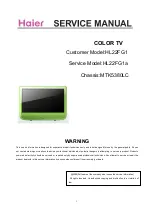


COLOR TV

Model No. : 
HL22FEP1

HL22FRR1 

HL22FRI1

HL22FPB1

CHASSIS:

 ZORAN775 

2009 (Qingdao Electronics 

limited company

 All rights reserved. Unauthorized copying and distribution is a violation of 

law. 


Summary of Contents for HL22FEP1

Page 1: ...service a product Products powered b electricity should be serviced or repaired only by experienced professional technicians Any attempt to service or repair the product deal with in this service information by anyone else could result in serious injury or death COLOR TV Model No HL22FEP1 HL22FRR1 HL22FRI1 HL22FPB1 CHASSIS ZORAN775 2009 Qingdao Electronics limited company All rights reserved Unaut...

Page 2: ...tion 7 3 2 A Board Main Boar 7 3 3 B Board Power Board 11 3 4 LCD Panel 12 4 Disassemble and assemble 14 4 1 Remove the Front Cabinet 14 4 2 Remove the LCD panel 14 4 3 Remove the Main Board 14 4 4 Remove the Power Board 15 4 5 Remove the Speaker 15 4 6 Remove the Keypad Assembly 15 4 7 Remove the Remote Control Board 15 5 Installation Instructions 16 5 1 External Equipment Connections 16 5 2 HDMI...

Page 3: ...agram 23 7 2 Circuit Diagram 23 7 3 Wiring Connection Diagram 37 8 Measurements and Adjustments 39 8 1 Version S N Panel Resolution 39 8 2 Video 39 8 3 Audio 40 8 4 Channel 41 8 5 Gamma 42 8 6 Backlight 43 8 7 Function 43 9 Trouble shooting 46 9 1 Simple check 46 9 2 Power Supply Board failure check 47 9 3 Main board failure check 48 9 4 Panel failure 50 ...

Page 4: ...t operating and maintenance instructions in the literture accompanying the appliance 1 2 2 Be careful to the electrical shock To prevent damage which might result in electric shock or fire do not expose this TV set to rain or excessive moisture This TV must not be exposed to dripping or splashing water and objects Filled with liquid such as vases must not be place on top of or above the TV 1 2 3 E...

Page 5: ... insulation resistance is less than M ohm the inspection repair should be required If you have not the 500V insulation resistance meter use a Tester External exposure metal Antenna terminal Headphone jack 1 2 8 Ordering Spare Parts Please include the following informations when you order parts Particularly the Version letter 1 Model number and Version letter The model number can be found on the ba...

Page 6: ...pic 2 Specification Model HL22FPB1 Screen size 21 6inch Aspect ratio 16 9 Resolution 1366 768 Contrast Ratio 1000 1 Angel of view H 170 V 160 Color display 16 7M OSD language English Color system ATSC NTSC Color Temperature Cold Standard Warm Audio output power Built in W 3W 2 Power Consumption in Standby 1W Total power input W 50W Voltage range V 120V 10 V Power frequency Hz 60HZ Time of sleep ti...

Page 7: ...3 LOCATION OF CONTROLS AND COMPONENTS 3 1 Board Location No Description A Board Main Board B Board Power supply Board C Panel 3 2 A Board Main Board 3 2 1 Function Description Main Board A Board B Board C ...

Page 8: ...8 Process signal which incept from exterior equipment then translate into signal that panel can display 3 2 2 Connector definition Main board connector LVDS Connector CN8 ...

Page 9: ...DS_D2E_N LVDS EVEN 2 Signal 12 LVDS_D2E_P LVDS EVEN 2 Signal 13 GND Ground 14 LVDS_CE_N LVDS EVEN Clock Signal 15 LVDS_CE_P LVDS EVEN Clock Signal 16 GND Ground 17 LVDS_D3E_N LVDS EVEN 3 Signal 18 LVDS_D3E_P LVDS EVEN 3 Signal 19 GND Ground 20 NC NC 21 NC NC 22 NC NC 23 GND Ground 24 GND Ground 25 GND Ground 26 Panel_power Power for panel 27 Panel_power Power for panel 28 Panel_power Power for pan...

Page 10: ...ERTER Lightness Adjust 5 BLON INVERTER Switch Control 6 12V 12V Power 7 12V 12V Power Audio Output Connector CN1 Pin number Signal name Description 1 LSPK Left Audio Output 2 GND Ground 3 GND Ground 4 RSPK Right Audio Output Remote Board and Key board Connector CN2 Pin Signal name Description PIN 1 PIN 1 PIN 1 ...

Page 11: ...t 4 GND Ground 5 LED_R Red Indicator light 6 K6 Key Connector POWER 7 K5 Key Connector MENU 8 K4 Key Connector P 9 K3 Key Connector P 10 K2 Key Connector V 11 K1 Key Connector V 12 K0 Key Connector SOURCE 3 3 B Board Power Board Supply power for Main board and Panel ...

Page 12: ...DJUST INVERTER Lightness Adjust 5 BL ON OFF INVERTER Switch Control 6 12V 12V Power 7 12V 12V Power Other Connector AC150V AC240V Input CN15 Power supply for panel CN11 Power supply for panel CN12 Power supply for panel CN13 Power supply for panel CN14 3 4 LCD PANEL LVDS Connector CN10 Connector definition PIN 1 CN10 ...

Page 13: ...13 ...

Page 14: ... indicated with Remover the six screws indicated with Then remove the front cabinet from the unit 4 2Remove the LCD panel Remover the six screws indicated with Then remove the panel 4 3Remove the Main Board Remover the four screws indicated with Remover the four screws indicated with ...

Page 15: ... 4 6Remove the Keypad Assembly Remover the two screws indicated with Then remove the Keypad Assembly 4 5Remove the Speaker Remover the four screws indicated with Then remove the Speaker 4 7Remove the Remote Control Board Remover the one screw indicated with Then remove the Remote Control Board ...

Page 16: ...picture quality from an antenna in a poor signal area install a signal amplifier If you need to split the antenna signal to connect two TVs install a two way splitter Choose Your Connection There are several ways to connect your television depending on the components you want to connect and the quality of the signal you want to achieve The following are examples of some different ways to connect y...

Page 17: ...e may be noise associated with the resolution vertical pattern contrast or brightness in PC mode If noise is present change the PC mode to another resolution change the refresh rate to another rate or adjust the brightness and contrast on the menu until the picture is clear If the refresh rate of the PC graphic card can not be changed change the PC graphic card or consult the manufacturer of the P...

Page 18: ...e box remote control Connection Option 2 1 Connect the audio and video cables from the Cable Box s output jacks to the TV input jacks as shown in the figure When connecting the TV to a Cable Box match the jack colors Video yellow Audio Left white and Audio Right red 2 Select the input source by using the button on the remote control 3 Select your desired channel with the remote control for cable b...

Page 19: ...pplied with this product 2 A separated audio connection is necessary 3 If the source device has an analog audio output connector connect the source device audio output to DVI Audio In port located on the left side of HDMI port How To Use If the source device supports Auto DVI function the output resolution of the source device will be automatically set to 1280x720p If the source device does not su...

Page 20: ...the AC cord plug into a standard polarized AC outlet NOTES Never connect the AC line cord plug to other than the specified voltage Use the attached power cord only If the polarized AC cord does not fit into a non polarized AC outlet do not attempt to file or cut the blade It is the user s responsibility to have an electrician replace the obsolete outlet If you cause a static discharge when touchin...

Page 21: ...te control Do not put anything near the sensor which may block the remote control signal COMPONENT IN Pr Pb Y ATN IN R AUDIO L R AUDIO IN L PCAUDIOIN VGA IN USB HDMI S VIDEO IN VIDEO 1 ANT IN Antenna Input Connect cable or antenna signals to the TV either directly or through your cable box 2 Headphone jack Headphone audio output terminal 3 Audio in Connect audio output from an external device to t...

Page 22: ... menu 6 Volume Channel Selection 7 Exit On Screen Display 8 Press to switch input source to USB in 9 DVD PLAY PAUSE 10 DVD fast reverse 11 DVD fast forward 12 Press to display the TV status information on the top of the TV screen 13 Shows program schedule in TV 14 Press to turn on and off the TV 15 Press to cycle through different sound settings 16 Press to display the sleep timer option 17 Select...

Page 23: ... 7 Electrical parts 7 1 Block diagram 7 2 Circuit Diagram HDMI1 VGA YPbPr S Video tuner Composite MT 5 3 8 0 LC Main IC YPbPr Composite L R VGA P11 L R DDR Flash TDA1517 P A N E L USB LVDS EEPROM I2C Bus ...

Page 24: ...A_6A L5 9 CN5 5PIN_2 0 CN5 5PIN_2 0 GND 3 5V 4 STB 5 12V 1 GND 2 U151 NTMD4840 U151 NTMD4840 3 2 1 4 6 5 8 7 E8 470uF 16V C330UF25V D8H14 E8 470uF 16V C330UF25V D8H14 C646 0 1uF C646 0 1uF T34 T34 R38 47K R38 47K R13 4 7K R13 4 7K R1697 4 7K R1697 4 7K T45 T45 Q44 2N3904 Q44 2N3904 1 3 2 T39 T39 T48 T48 Q5 2N3904 SOT23 Q5 2N3904 SOT23 3 1 2 U152 NCP1579 U152 U152 NCP1579 U152 BST 1 TG 2 GND 3 BG 4...

Page 25: ... 2K_1 R10 110_1 R10 110_1 CB10 0 1uF CB10 0 1uF R519 100K R519 100K R1 110_1 R1 110_1 CB64 0 1uF CB64 0 1uF U11 LT1084 TO 252 3 U11 LT1084 TO 252 3 IN 3 ADJ GND 1 OUT 2 R11 180_1 R11 180_1 R47 100K 1 R47 100K 1 C301 0 1uF C301 0 1uF CE33 470uF 16V C330UF25V D8H14 CE33 470uF 16V C330UF25V D8H14 R5 1K_1 R5 1K_1 CB33 0 1uF CB33 0 1uF CE7 47uF 16v CE7 47uF 16v CE17 100uF 16v CE17 100uF 16v C302 NC C30...

Page 26: ...LOG POWER 1 25 x 1 180 110 3 3V 1 25 x 1 100 100 2 5V 1 25 x 1 0 100 1 25V 10 tolerance R12 110_1 R12 110_1 U10 AZ1117 adj U10 AZ1117 adj ADJ GND 1 OUT 2 IN 3 CB32 0 1uF CB32 0 1uF CB228 0 1uF CB228 0 1uF R14 180_1 R14 180_1 R19 0R R19 0R C575 1uF C575 1uF U7 AZ1117 adj U7 AZ1117 adj ADJ GND 1 OUT 2 IN 3 CE19 470uF 16V C330UF25V D8H14 CE19 470uF 16V C330UF25V D8H14 CB229 0 1uF CB229 0 1uF CE22 100...

Page 27: ...8 10K R28 10K R52 NC R52 NC TP34 TP34 C21 5pF 20pF C21 5pF 20pF R22 47K R22 47K R198 10K R198 10K R40 4 7K R40 4 7K R2021 0R NC R2021 0R NC C22 1uF C22 1uF R27 1 R27 1 H3 HOLE GND H3 HOLE GND 2 2 3 3 4 4 5 5 9 9 8 8 7 7 6 6 1 1 FB17 FB FB17 FB Q1 2N3904 Q1 2N3904 1 3 2 R199 NC R199 NC R25 390 R25 390 CB70 0 1uF CB70 0 1uF R21 220 R21 220 Y1 60MHz Y1 60MHz R30 33 R30 33 TP36 TP36 R35 NC R35 NC H4 H...

Page 28: ...27pF C57 4 7uF C57 4 7uF R168 NC 10K R168 NC 10K C31 4 7uF C31 4 7uF R188 0R NC R188 0R NC T57 T57 F2 Little 1206L110 C POLYFUSE1206 SMD F2 Little 1206L110 C POLYFUSE1206 SMD T22 T22 CB197 0 1uF CB197 0 1uF L12 390nH L12 390nH FB48 FB FB48 FB FB19 FB FB19 FB FB61 NS FB FB61 NS FB R2038 0R NC R2038 0R NC CB137 0 1uF CB137 0 1uF CE847 10uF 16v CE847 10uF 16v C38 33pF C38 33pF C108 NC 330nF C108 NC 3...

Page 29: ... 47x4 0402 RN0402 SMD RNA10 47x4 0402 RN0402 SMD 1 2 3 4 5 6 7 8 RNA17 75x4 RNA17 75x4 1 2 3 4 5 6 7 8 CA20 0 1uF CA20 0 1uF CA5 0 1uF CA5 0 1uF RA8 75 RA8 75 RNA4 47x4 0402 RNA4 47x4 0402 1 2 3 4 5 6 7 8 RA7 75 RA7 75 RNA6 47x4 0402 RNA6 47x4 0402 1 2 3 4 5 6 7 8 RA14 100 RA14 100 CA27 0 1uF CA27 0 1uF UA1 16M x 16 DDR TSOP 66 UA1 16M x 16 DDR TSOP 66 VDD 1 DQ0 2 VDDQ 3 DQ1 4 DQ2 5 VSSQ 6 DQ3 7 D...

Page 30: ...RI 93 T8 T8 R1209 0R R1209 0R R1257 NS 4 7K R1257 NS 4 7K R45 4 7K R45 4 7K R54 10K R54 10K R61 10K R61 10K T7 T7 U17 M25L3205D U17 M25L3205D S_ 1 Q 2 W_ VPP 3 VSS 4 D 5 C 6 HOLD_ 7 VCC 8 R1227 NS 4 7K R1227 NS 4 7K CB452 0 1uF CB452 0 1uF T9 T9 CB52 0 1uF CB52 0 1uF R197 NS 10K R197 NS 10K RN5 10Kx4 RN5 10Kx4 1 2 3 4 5 6 7 8 CA36 4 7uF CA36 4 7uF CA37 0 1uF CA37 0 1uF CB53 0 1uF CB53 0 1uF CA39 0...

Page 31: ...C 14 DDC CLK 15 DDC DATA 16 GND 17 5V 18 HP DET 19 SHELL3 22 SHELL4 23 D199 D199 1 2 R2112 0 R2112 0 R2066 1K NS R2066 1K NS R2085 47K R0603 SMD R2085 47K R0603 SMD R2123 68R R2123 68R R2114 1K NS R2114 1K NS C176 1uF C0402 SMD C176 1uF C0402 SMD D153 RB520S 30 1N4148 SMD D153 RB520S 30 1N4148 SMD 1 2 R2027 100K R2027 100K C715 100nF C0402 SMD C715 100nF C0402 SMD R2083 0 R0603 SMD R2083 0 R0603 S...

Page 32: ...h panel with TCON CMO D2 1N4148 D2 1N4148 Q28 2N3904 Q28 2N3904 1 3 2 CE72 470uF 16v C330UF25V D8H14 CE72 470uF 16v C330UF25V D8H14 CB155 0 1uF CB155 0 1uF R391 NC R391 NC Q9 2N7002 Q9 2N7002 1 3 2 T6 T6 R394 10k R394 10k CB154 0 1uF CB154 0 1uF R397 10K R397 10K FB55 FB FB55 FB CB152 0 1uF CB152 0 1uF R396 4 7k R396 4 7k Q26 2N3904 Q26 2N3904 1 3 2 C85 1uF C85 1uF R401 10K R401 10K CB216 0 1uF CB...

Page 33: ...pF C594 18pF C363 10nF C363 10nF FB42 FB FB42 FB D105 ESD_0402_10pF C0402 SMD D105 ESD_0402_10pF C0402 SMD 1 2 C351 10nF C351 10nF CB158 0 1uF CB158 0 1uF C596 10nF C596 10nF R1192 68 R1192 68 T24 T24 FB40 FB FB40 FB C598 10nF C598 10nF C597 18pF C597 18pF C658 10uF 10v C0805 SMD C658 10uF 10v C0805 SMD R1643 20K R1643 20K R1642 20K R1642 20K D158 ESD_0402_10pF D158 ESD_0402_10pF 1 2 CB160 0 1uF C...

Page 34: ...5 NS 0 1uF R24 10K R24 10K R170 2K R170 2K C134 5pF C134 5pF C135 10nF C135 10nF D31 ESD_0402_10pF D31 ESD_0402_10pF 1 2 R169 68 R169 68 R160 0R R160 0R R181 0R R181 0R R171 75 R171 75 R182 10K R182 10K C137 5pF C137 5pF R161 0R R161 0R QF6 2N7002 SOT23 SMD QF6 2N7002 SOT23 SMD 1 3 2 C136 10nF C136 10nF P11 SLIM_phonejack P11 SLIM_phonejack HP 1 GND 2 NC 3 NC 4 L 5 R 6 L 7 R106 nc R106 nc D23 ESD_...

Page 35: ...SMD C663 10uF 10v C0805 SMD R1591 47 R1591 47 C534 47nF C534 47nF R1587 100 R1587 100 R1594 27 R1594 27 T61 T61 C152 4 7uF C152 4 7uF R1592 100 R1592 100 C459 47pF C459 47pF TP51 TP51 R1525 47 R1525 47 T63 T63 D147 ESD_0402_10pF D147 ESD_0402_10pF 1 2 R1560 100 R1560 100 CB163 0 1uF CB163 0 1uF CB162 0 1uF CB162 0 1uF R1562 47 R1562 47 D146 ESD_0402_10pF D146 ESD_0402_10pF 1 2 R1598 27 R0603 SMD R...

Page 36: ... 174 AIN3_L 173 AIN3_R 172 AVDD33_AADC 171 AVSS33_AADC 183 VMID_AADC 181 REFP_AADC 182 REFN_AADC 180 ASPDIF 203 AOMCLK 200 AOLRCK 201 AOBCK 202 AOSDATA0 198 AL1 188 AR1 187 AL2 191 AR2 189 AVDD33_ADAC0 192 AVDD33_ADAC1 184 AVSS33_ADAC0 190 AVSS33_ADAC1 186 ADAC_VCM 185 AVDD33_DIG 170 C603 0 1uF C603 0 1uF T88 T88 T101 T101 R33 1K R33 1K C329 4 7uF C329 4 7uF T84 T84 T4 T4 U2 TPA1517 TDA1517P U2 TP...

Page 37: ...K C668 10uF 10v C0805 SMD C668 10uF 10v C0805 SMD R298 5 1K R298 5 1K CE25 470uF 16V C330UF25V D8H14 CE25 470uF 16V C330UF25V D8H14 U55A NJM4558 OPA U55A NJM4558 OPA 3 2 1 8 4 D15 1N4148 D15 1N4148 C670 10uF 10v C0805 SMD C670 10uF 10v C0805 SMD C650 0 1uF C650 0 1uF T74 T74 C643 120pF C0603 SMD C643 120pF C0603 SMD CE3 47uF 16v CE3 47uF 16v R1644 10k R1644 10k C694 10uF 10v C0805 SMD C694 10uF 10...

Page 38: ...Power supply board LVDS wire Speaker wire Speaker Power cord Keypad Assembly Remote Control Board Assembly Combination wire Power supply and inveter 10 8 9 7 3 CN10 CN15 1 CN2 4 2 6 5 1 2 3 4 5 6 7 8 9 10 0090701136 CN11 CN6 1 1 1 1 1 1 2 1 1 1 HAC 32 0090719615 0094001227CA 0094001224B 0090402338 HL22FPB1 LA22F3W DC14C0E0900 AT08SR1101US46 DC14C0E0900M 0090402274 0094015071 0090403157C 0090719341...

Page 39: ...e factory mode menu 1st press nemu 2en input 8893 Finished these operations system will be into the factory mode menu 8 1 Version S N Panel Resoution Version The first line is the model Name and the second line is current software version 8 2 Video ...

Page 40: ...2 2 Color Temperature The function could adjust the Color Temperature used when debugging 8 3 Audio Dolby Banner When turn it ON the model will be in Dolby authentication state Compression Compression style RF Atv line AV S Video YPbPr VGA USB Compression Factor Compression state Downmix output model MTS System used when debugging The parameters only used when debugging no need to be modified ...

Page 41: ...3 8 4 Channel Range Scan The function could make it to search the channels by differentiation the analog and digital channels Single RF Scan Search channels in the frequency scope set in advance ...

Page 42: ...A DIGITAL CABLE ANALOG CABLE DIGITAL to search channels used only in project debugging Tuner Diagnostic Project debugging setting used to inspect the audio function 8 5Gamma Gamma Bright GAMMA0 8 Middle default settings in the programme Dark GAMMA1 2 ...

Page 43: ...5 8 6 Backlight Backlight adjust the backlight 8 7 Function ...

Page 44: ...g model This is for factory run in testing The screen would display red green blue and black screen repeatedly Each color screen could be exam at that time Clean Storage The function could make the model turn back to the factory default setting ...

Page 45: ...7 Remark The date of the chart only is a example please don t adjust the factory mode base on it ...

Page 46: ...if the same problem happens Press VOL button to see of he problem can be solved Poor sound Verufy if sound system is correct Refer to some chapter for adjust No picture in some channel Verify if correct channel is selected Adjust the antenna Make adjustments by Fine Tune and MANUAL Scan No color for some channel program black and white Verify if the same problem exists in other channels check out ...

Page 47: ... follow F1 Check U6 MCU 1 Power supply U7 U9 2 Reset signal 3 Crystal LDO was damaged or the loader is in short circuit OK Check U1 for 5V output Change U1 MP1410ES LF or D17 SK34A SMA Check L9 47μH It s normal but the voltage is high It s normal but the voltage is Low Check Pin No 4 of U1 MP1410 ES or change U1 E33 was damaged or the loader is in short circuit Y N Y N N Y Y N Y N Y N 9 2 Power Su...

Page 48: ...k the input Source Change Source input Check the input output Of IC U13 of Main B D Re soldering or change IC U13 Check the input output Of IC U55 of Main B D Re soldering or change IC U55 Check the input output Of IC U2 of Main B D Re soldering or change IC U2 Check the Speaker Change the Speaker Check the Sperker wire ...

Page 49: ...el Check the backlight B D Change the backlight B D Check the input output of jack CN3 of Main B D Re soldering or change IC UA1 and RNA1 17 Check the input output of Jack CN4 of Main B D Re soldering or change IC U13 Change the panel Change the Panel wire Check the Panel wire ...

Page 50: ...t Awful environment and something electric enter into LCD Mis align between TCP and Panel Panel failure TCP failure Failure Mode Part Name Description Phenomena Failure cause Dot Defect Bright dot dark dot in pannel Incoming Inspection Standard Polarizer Bubble Bladder in Polarizer Bladder between Polarizer and top glass Polarizer Scratch Polarizer Scratch Tine or rigidity arose Panel or Polarlzer...

Page 51: ...inside LCD pannel Circuit Abnormal Color Only color abnormal 1 Chip lose action 2 IC short or jointion bad 3 Pannel and vsc connect bad Failure Mode Part Name Description Phenomena Failure cause Mechanlcal Nolse When turn panel appear cacophony Caused by Mechanica noise of backlight unit Ripple Connectric circle Causeed by between mechanism and pannel B L off B L lose action Connect badness betwee...

Page 52: ... power too much F M F M in B L white balck Rotundity or wirelike F M in B L unit Failure Mode Part Name Description Phenomena Failure cause Light leakage Brightness at bottom of LCM brighter than normal B L unit badness Uniformity B L brightness asymmetric Sheet in B L unit is uneven Mechanlcal or B L Mount hole Lack screw or screw damage Lack screw Screw damage ...

Page 53: ...48 Sincere Forever Haier Group Haier Industrial Park No 1 Haier Road 266101 Qingdao China http www haier com ...

Reviews: