Haier HL19T, Service Manual
The Haier HL19T Service Manual is a valuable resource for users seeking in-depth knowledge about this product. With a simple download from our website, users can access this manual for free. Discover detailed instructions, troubleshooting tips, and essential information to maximize your experience with the Haier HL19T.
Share
Download


Reviews:
No comments
Related manuals for HL19T
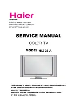
HL32S-A
Brand: Haier Pages: 44
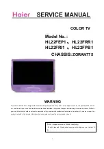
HL22FEP1
Brand: Haier Pages: 53
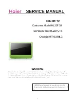
HL22FG1
Brand: Haier Pages: 7

HL26K
Brand: Haier Pages: 42

HL32S-A
Brand: Haier Pages: 44

HL42T
Brand: Haier Pages: 46
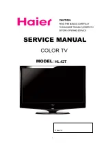
HL42T
Brand: Haier Pages: 53
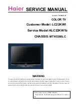
HLC22KW1b
Brand: Haier Pages: 50
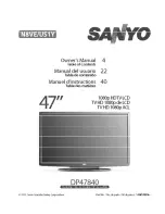
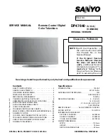
DP47840
Brand: Sanyo Pages: 56
DP47840
Brand: Sanyo Pages: 43

32A32
Brand: Toshiba Pages: 36

32A32
Brand: Toshiba Pages: 33
HL22FG1
Brand: Haier Pages: 50

HL22FG1
Brand: Haier Pages: 84

40PFK6580
Brand: Philips Pages: 145

CI21N112TZXXEU
Brand: Samsung Pages: 29
BRAVIA KD-85X9500B
Brand: Sony Pages: 127
DS19330
Brand: Sanyo Pages: 40


