background image


 HL15R 


TV-8888-127

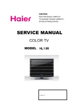
Summary of Contents for HL15R - 15" LCD TV

Page 1: ...1 HL15R TV 8888 127 ...

Page 2: ...CATION OF CONTROLS AND COMPONENTS 8 3 1 Board Location 8 3 2 Main Board 7 3 3 Power Board 11 3 4 LCD Panel 12 4 FEATURES AND TECHINICAL DESCRIPTION 14 5 INSTALLATION INSTRUCTIONS 14 6 External Equipment Connections 21 7 OPERATION INSTRUCTIONS 26 7 1 Front Panel Controls 26 7 2 Back Panel Controls 27 7 3 Universal Remote Controller 28 8 DISASSEMBLY INSTRUCTIONS 29 8 1 Whole Machine 29 8 2 Base Suba...

Page 3: ...2 12 2 Power Supply Board failure 42 12 3 Main board failure check 43 12 4 Pannel failure 43 12 MAINTENANCE 46 ...

Page 4: ...of preset channels 181 OSD language English Spanish French Color system NTSC Audio system M Audio output power Built in W 2 1 5W Audio output power outer W No Total power input W 50W Voltage range V AC120V Power frequency Hz 60Hz Time of sleep timer MINS 240Min Net weight KG 2 2 Gross weight KG 3 Net dimension MM 381 147 330 Packaged dimension MM 439 167 475 ...

Page 5: ...uctfrom being damaged the following rules should be observed for the installation use and maintenance of th product Read the following safety instruction before starting the operation The User Manual uses the following symbols to ensure a safe operation and preventany damage to operators or properties THIS SYMBOL INDICATES THAT HIGH VOLTAGE IS PRESENT INSIDE IT IS DANGEROUS TO MAKE ANY KING OF CON...

Page 6: ...e These limits are designed to provide reasonable protection against harmful interference in a residential installation This equipment generates use and can radiate radio frequency energy and if not installed and used in accordance with the instructions may cause harmful interference to radio communications However there is no guarantee that interference with not occur in a particular installation...

Page 7: ...ne surges 12 Never push objects of any kind into this product through openings as they may touch dangerous voltage point or short out parts that could result in a fire or electric shock Avoid spilling liquid of any kind on the product 13 Servicing do not attempt to service the product by yourself as opening or removing covers may expose you to dangerous voltage or other hazards Refer all servicing...

Page 8: ...duct Remember to record the model and serial number They are on label in back of the unit Staple your receipt to your manual You will need it to obtain warranty service 3 LOCATION OF CONTROLS AND COMPONENTS 3 1 Board Location No Parts number Description A Board Main Board B Board Power Board 3 2 A Board Main Board ...

Page 9: ... TFT LCD Panel through the power supply unit path CN3 Pin 7 System power on standby System board will use this pin to control system power CN3 Pin 4 Control the luminance of backlight The system can generate the PWN signal to control the strength of TFT LCD Panel s backlight through this connector TFT LCD Panel LVDS Connector CN4 CN3 CN5 Pin number Signal name Pin number Signal name 1 12VEXT 1 12V...

Page 10: ...2 LVDS EVEN 2 Signal 13 14 GND Ground 15 RXEC LVDS EVEN Clock Signal 16 RXEC LVDS EVEN Clock Signal 17 RXE3 LVDS EVEN 3 Signal 18 RXE3 LVDS EVEN 3 Signal 19 RXO0 LVDS ODD 0 Signal 20 RXO0 LVDS ODD 0 Signal 21 RXO1 LVDS ODD 1 Signal 22 RXO1 LVDS ODD 1 Signal 23 RXO2 LVDS ODD 2 Signal 24 RXO2 LVDS ODD 2 Signal 25 26 GND Ground 27 RXOC LVDS ODD Clock Signal 28 RXOC LVDS ODD Clock Signal 29 RXO3 LVDS ...

Page 11: ... 4 GND GND 5 PR_IN PR1 IN 6 GND GND 7 IR DVD IR DVD AUDIO Connector P1 Pin number Signal name Description 1 LI YPBPR1L_IN 2 RI YPBPR1R_IN 3 GND GND Other connectors 1 CN19 to Upgrade the program of MTK5380 U13 AND FLASH U17 U0TX 3V3SB U0RX J3 4x1 W HOUSING DIP4 W H P2 0 1 2 3 4 3 3 B Board Power Board ...

Page 12: ...tion Supply power for Main board Panel 3 3 2Connectordefinition INPUT CONNECTOR CN6 3 4 LCD PANNEL 3 4 1 Function Description Display the signal 3 4 2 Connector definition CN6 Signal name 1 N 2 GND 3 GND 4 DIM 5 EN 6 12V 7 12V ...

Page 13: ...RXE1 LVDS EVEN 1 Signal 10 RXE1 LVDS EVEN 1 Signal 11 RXE2 LVDS EVEN 2 Signal 12 RXE2 LVDS EVEN 2 Signal 13 14 GND Ground 15 RXEC LVDS EVEN Clock Signal 16 RXEC LVDS EVEN Clock Signal 17 RXE3 LVDS EVEN 3 Signal 18 RXE3 LVDS EVEN 3 Signal 19 RXO0 LVDS ODD 0 Signal 20 RXO0 LVDS ODD 0 Signal 21 RXO1 LVDS ODD 1 Signal 22 RXO1 LVDS ODD 1 Signal 23 RXO2 LVDS ODD 2 Signal 24 RXO2 LVDS ODD 2 Signal 25 26 ...

Page 14: ... appointments are now available Note This information is provided to help guide your installation Haier assumes no liability for errors or the outcome of any installation since each project is unique and tools materials techniques local codes and regulations vary and change Preparing for Your Installation In planning your flat panel television install there are some questions you ll need to ask yo...

Page 15: ...It is necessary to have proper support for your TV In most cases there will be wood metal or mortar to mount the bracket to TV Breakdown See our TV Selection LCD TVs 32 and smaller This type of TV is clean looking and lightweight They are usually easier to mount and require smaller brackets LCD TVs 32 and larger This type of TV is a larger version of their smaller counterparts They are usually mor...

Page 16: ... out by the NEC and in any local restriction codes it is strongly recommended that you make use of a professional installer if you re unsure of local ordinances Wire Running Techniques Beginner Skill Level 1 or 2 hours depending on room Track molding This concealment option is an adhesive backed hollow plastic trim that can hold wiring on the inside When the wires are run inside the trim the adhes...

Page 17: ... Note This information is provided to help guide your installation Haier assumes no liability for errors or the outcome of any installation since each project is unique and tools materials techniques local codes and regulations vary and change Preparing for Your Installation In planning your speaker installation there are some questions you ll need to ask yourself first Once these are answered you...

Page 18: ...om Proper treatment will cut down unwanted noise as well as help your sound quality A working knowledge of your house s construction Before you begin installation know what is hidden before you cut or drill This will help avoid any costly uses of the word oops Needed ToolsSome tools used in the installation profession can cost hundreds of dollars However these tools can save hours of work on a pro...

Page 19: ...ccess from a basement or attic to run wires up or down a wall Interior walls are usually empty but exterior walls will often be blocked with insulation TECHTIP If you have access to a wall where you need a wire fished drill up from the lower level or down from an upper level into the center of the wall Once you have an access hole drilled run your wire fish tool such as a flex rod down to where yo...

Page 20: ...and gas lines air vents drain lines many of these will not register with a stud finder but can hide an inch or two behind the sheetrock It s best to find this out with a small hole you can easily fix rather than a full sized hole that needs involved repair 3 After you verify the cavity is free of obstructions use your drywall saw to begin cutting your hole TECHTIP Cut as you push in cutting as you...

Page 21: ...hough the speaker may be level a bookcase or anything else in the room that is not level can make a level speaker look crooked Have someone stand back as you hold it to make sure it looks good with the rest of the room 8 Once you have tightened your speaker into place the last step is to insert the grille that came with your speaker This is a decorative cover that conceals the components of the sp...

Page 22: ...tion which is best for you VCR connection To avoid picture noise interference leave an adequate distance between the VCR and TV Connection Option 1 Set VCR output switch to channel 3 or 4 and then tune the TV to the same channel number Connection Option 2 1 Connect the audio and video cables from the VCR s output jacks to the TV input jacks as shown in the figure When connecting the TV to VCR matc...

Page 23: ...bPr Audio IN jacks on the TV as shown in the figure 2 If your DVD only has an S VIDEO output jack connect this to the S VIDEO input on the TV as shown in the figure NOTE If your DVD player does not have component video output use S Video How to use 1 Turn on the DVD player insert a DVD 2 Use the INPUT button on the remote control to select YPbPr mode 3 Press Play button on external equipment for p...

Page 24: ...ernal audio equipment instruction manual for operation Note When connecting with external audio equipments such as amplifiers or speakers please turn the TV speakers off Caution Do not look into the optical output port Looking at the laser beam may damage your vision PC Connection How to connect 1 To get the best picture quality adjust the PC graphics card to 1024x768 2 Use the TV s PC or DVI Digi...

Page 25: ...the PC graphic card NOTES 1 Use a DVI cable 2 Avoid keeping a fixed image on the TV s screen for a long period of time The fixed image may become permanently imprinted on the screen 3 The synchronization input form for Horizontal and Vertical frequencies is separate R esolution Frame frequency Hz VGA SVGA XGA 640 480 60Hz 800 600 60Hz 75Hz 1024 768 60Hz Mode Resolution 75Hz 85Hz Connecting Headpho...

Page 26: ...le or cut the blade It is the user s responsibility to have an electrician replace the obsolete outlet If you cause a static discharge when touching the unit and the unit fails to function simply unplug the unit from the AC outlet and plug it back in The unit should return to normal operation Take the table stand off You can take off the table stand if you don t want to use the table stand HL15R P...

Page 27: ...27 7 2 Back panel controls ...

Page 28: ...28 7 3 Setting Up Your Remote Control ...

Page 29: ...hine The whole machine includes Packaging subassembly Front frame subassembly Back cover subassembly Base subassembly MAINBOARD SUBASSEMBLY Remote Control Board Subassembly Control Board Subassembly Assembly Material Subassembly Romoter Contral ...

Page 30: ...on Parts number 1 HL15R whole machine 2 Packaging 3 TV Set 3 1 Base subassembly 3 2 Back cover subassembly 3 3 Front Frame Subassembly 3 4 Assembly Material Subassembly 3 5 Control Board Subassembly 3 6 Remote Control Board Subassembly 3 7 Mainboard Subassembly 8 2 Base subassembly ...

Page 31: ...ification Qty Base Subassembly 1 Base Assembly 1 Base Borad 1 Bolt M3 16 1 Base Subassembly Rubber 4 8 3 Back cover subassembly Components List Subassembly Spare parts number Location No Spare Parts Name in English Specification Qty Back Cover Subassembly Back Cover Subassembly 1 ...

Page 32: ...Terminal Board 1 Rotational Axis 2 Bolt SJ2824 87 ST3X10F 8 Plastic board 1 Bolt SJ2824 87 ST4 16F 1 Bolt SJ2825 87 ST3X120F 2 Terminal Lable 1 Metal clip 2 Bolt SJ2824 87 ST3X8F 2 Label 1 8 4Front frame subassembly Components List Subassembly Spare parts number Location No Spare Parts Name in English Specification Qty ...

Page 33: ... 1 Transparent Window 1 LCD panel bracket 2 Metal piece 2 Bolt 8 Bolt SJ2824 87 ST3 8F 2 Speaker Wire JT4801 J3750Y 1 Speaker Y37 2W 4OHM 2 Front Frame Subassembly Bolt SJ2824 87 ST3 10F 4 8 5 Assembly Material Subassembly 8 5 1 Location Photo 8 5 2 Components List ...

Page 34: ...m TJC3 7 1 Power Supply Board PCA050FA 011 P R 1 Left Gasket EPS 1 Right Gasket EPS 1 LCD PANNEL 1 Bolt SJ2824 87 ST3 8F 8 Bolt SJ2824 87 ST3X10F 8 Bolt SJ2824 87 ST3X10F 6 Magnetism Coil BCRK 513571 1 Magnetism Coil BCRK 513571 1 Assembly Material Subassembly Electric Sponge 1 9 MEASUREMENTS AND ADJUSTMENTS The way to the factory mode menu 1st press nemu 2en input 8893 Finished these operations s...

Page 35: ...ame and the second line is current software version 9 2 Video 9 2 1 Auto Color The option could only be used in the VGA and Component model When we found the color in the two models was abnormal Then we can use the function to adjust it automatically 9 2 2 Color Temperature ...

Page 36: ...er When turn it ON the model will be in Dolby authentication state Compression Compression style RF atv line AV S Video YPbPr VGA Compression Factor Compression state Downmix output model MTS System used when debugging The parameters only used when debugging no need to be modified 9 4 Channel ...

Page 37: ...nnels by differentiation the analog and digital channels Single RF Scan Search channels in the frequency scope set in advance Factory Scan According to ANTENNA ANALOG ANTENNA DIGITAL CABLE ANALOG CABLE DIGITAL to search channels used only in project debugging ...

Page 38: ...ner Diagnostic Project debugging setting used to inspect the audio function 9 5Gamma Gamma Bright GAMMA0 8 Middle default settings in the programme Dark GAMMA1 2 9 6 Backlight Backlight adjust the backlight ...

Page 39: ...7 Function Burning Mode Turn it ON to enter the aging model This is for factory run in testing The screen would display red green blue and black screen repeatedly Each color screen could be exam at that time ...

Page 40: ... Clean Storage The function could make the model turn back to the factory default setting Remark The date of the chart only is a example please don t adjust the factory mode base on it 10 CIRCUIT DIAGRAM ...

Page 41: ..._IN PR1_IN OIRI GPIO_11 Y1_IN DVD_IR GPIO_11 Y1_IN PB1_IN PR1_IN SW_POWER 5VSB OIRI 3V3SB DVD_IR OPWRSB OPWRSB OIRI 7 GND 2 3 4 5 6 7 8 9 10 11 12 13 14 3V3SB 2 4 7 8 9 13 OPCTRL3 4 5VSB 2 7 9 11 ADIN2 4 12V 2 3 8 9 14 ADIN1 4 5V 2 3 5 8 9 13 14 BL_ON OFF 9 DIMMING 9 GPIO_3 4 GPIO_10 4 GPIO_11 4 PB1_IN 10 PR1_IN 10 Y1_IN 10 OPWRSB 4 3V3SB DC 12V DC 12V 5VSB 12V DC 12V 3V3SB 5V 5V_DVD 5VSB 3V3SB 3V...

Page 42: ... DV33 12V DV10 DDRV VTT 5V DDRV DDRV AV33 CE593 470uF 16v R29 NC R956 110 R43 1 5K CB12 0 1uF R32 NC L134 NC CB37 0 1uF R10 110 R7 2K R519 100K U4 IC LP2996 DDR Termination SOP 8 1 2 3 4 5 6 7 8 GND SD VSENSE VREF VDDQ AVIN PVIN VTT R1 110 CB64 0 1uF U11 LT1084 TO 252 3 3 1 2 IN ADJ GND OUT R11 180 C301 NS 100nF CE33 470uF 6 3v CB33 0 1uF R5 1K CB8 0 1uF R6 4 7K CE17 100uF 10v C302 NC CE15 100uF 6...

Page 43: ... 6 7 8 9 10 11 12 13 14 5V 1 2 5 8 9 13 14 AV33 2 5 8 9 13 AV12 5 8 10 5V_TUNER 5 12 AV25 5 12 12V 1 8 9 14 OPWM2 4 7 5V AV33 AV25 5V 5V_TUNER AV12 AV25 12V R12 110 U10 AZ1117 adj 1 2 3 ADJ GND OUT IN CB32 0 1uF R14 180 CB228 0 1uF CB197 0 1uF R19 0 C575 1uF U7 AZ1117 adj 1 2 3 ADJ GND OUT IN CB229 0 1uF CE19 470uF 6 3v CE22 100uF 10v C573 1uF CE30 100uF 10v CE28 100uF 6 3v U56 7805 TO 263 3 SMD 1...

Page 44: ...0 7 ADIN1 1 ADIN2 1 OPCTRL3 1 GPIO_3 1 GPIO_10 1 GPIO_11 1 DV33 3V3SB DV33 3V3SB 3V3SB 3V3SB DV33 DV33 DV33 3V3SB H2 HOLE GND 2 3 4 5 9 8 7 6 1 2 3 4 5 9 8 7 6 1 R52 NC R28 10K TP34 C21 5pF R22 47K R40 4 7K R198 10K R27 1 C22 1uF FB17 FB H3 HOLE GND 2 3 4 5 9 8 7 6 1 2 3 4 5 9 8 7 6 1 Q1 2N3904 1 3 2 R199 NC R25 390 TP36 R21 220 CB70 0 1uF Y1 60MHz R30 33 R35 NC H4 HOLE GND 2 3 4 5 9 8 7 6 1 2 3 4...

Page 45: ...IFN TUNER_CLK AF AVDD25_SADC CB450 NS 100pF T1 TUNER_ALPS TH1 TH2 TH3 TH4 1 2 3 4 5 6 7 8 11 12 13 14 15 16 17 18 19 20 21 GND1 GND2 GND3 GND4 NC or OOB B1_ 5V GND or SIF O P GND or CVBS RF_AGC Mon NC or AFT NC or IF_AGC Mon NC or B2_Ana_ 5V TU_ 32V GND GND SCL SDA AS B_IF O P D_IF_AGC NC D_IF_O P_1 D_IF_O P_2 C41 1uF C42 0 01uF C0603 SMD CE38 100uF 6 3v C70 10nF R34 5 1K 1 FB34 FB R1159 220K C75 ...

Page 46: ...8 9 10 11 12 13 14 MEM_VREF 2 VTT 2 VTT DDRV VTT DDRV DDRV VTT VTT RA6 75 CA3 0 1uF 0402 CA23 4 7uF 10V RA10 NS 75 RNA1 47x4 0402 1 2 3 4 5 6 7 8 RNA10 47x4 0402 RN0402 SMD 1 2 3 4 5 6 7 8 RNA17 75x4 1 2 3 4 5 6 7 8 CA20 0 1uF CA5 0 1uF 0402 RA8 75 RNA4 47x4 0402 1 2 3 4 5 6 7 8 RA7 75 RNA6 47x4 0402 1 2 3 4 5 6 7 8 RA14 100 CA27 0 1uF UA1 16M x 16 DDR TSOP 66 1 2 3 4 5 6 7 8 9 10 11 12 13 14 15 1...

Page 47: ...T5380 SMD LQFP 252 251 250 249 95 94 253 1 256 255 254 93 POCE0_ POOE_ PDD0 PDD1 U0RX U0TX JTMS JTRST_ JTCK JTDO JTDI OIRI R1209 0 R1257 NS 4 7K R45 4 7K R54 10K R61 4 7K U17 M25P16 NS 1 2 3 4 5 6 7 8 S_ Q W_ VPP VSS D C HOLD_ VCC R1227 NS 4 7K CB452 0 1uF CB52 0 1uF C0402 SMD R197 NS 10K RN5 10K X4 1 2 3 4 5 6 7 8 CA36 4 7uF 10V CA37 0 1uF C0402 SMD CB53 0 1uF C0603 SMD CA39 0 1uF C0603 SMD C45 1...

Page 48: ...2V 12V 3V3SB 12VAMP 12V 12V C17 4 7uF 10v CB146 0 1uF C0603 SMD U23 EEPROM 24C02 1 2 3 4 5 6 7 8 NC NC NC GND SDA SCL WP VCC CE8 470uF 16v R97 1K DN2 PESD1206Q 140 PESD1206Q 140 SMD 1 2 3 4 5 6 7 8 R94 20K R33 1K C655 10uF 10v C0805 SMD R96 47K R625 4 7K L142 FB U2 TPA1517 TDA1517P 1 2 3 4 5 6 7 8 9 10 11 12 13 14 15 16 17 18 19 20 IN1 SGND SVRR OUT1 GND OUT2 VPP MUTE IN2 GND GND GND GND GND GND G...

Page 49: ...4 DIMMING 1 BL_ON OFF 1 5V_LVDS 12V AV33 AV33 5VSB 3V3SB DV33 5V 5V 5V 12V 12V 5V_LVDS CB218 0 1uF TP45 C654 100nF C0603 SMD CB155 0 1uF C0603 SMD CB216 0 1uF TP46 CN4 15x2 DIP 15X2P P2 0 2 4 6 8 10 12 14 16 18 20 22 24 26 28 30 1 3 5 7 9 11 13 15 17 19 21 23 25 27 29 JP10 FB 1206 CB455 1uF R123 100K L132 FB D164 SCHOTTKY DIODE B340A D SMA SMD CE72 470uF 16v R401 10K R1789 4 3K R0603 SMD Q28 2N390...

Page 50: ...40 80 100MHZ R1200 68 C659 10uF 10v C0805 SMD R1641 68 TP47 L82 80 100MHZ C115 1uF C351 10nF C349 4 7nF D105 NS EZJZ0V800AA ESD0603 SMD 1 2 C592 4 7nF R1635 100 R1639 100 R1184 68 C363 10nF C353 15pF R1640 75 R1636 68 D157 NS EZJZ0V800AA 1 2 R153 20K D160 NS EZJZ0V800AA ESD0603 SMD 1 2 R1203 75 C357 10nF D156 NS EZJZ0V800AA 1 2 R1189 100 C116 1uF CB160 0 1uF C0603 SMD C600 10nF C598 10nF L81 80 10...

Page 51: ...VGA_PLUGPWR VGA_PLUGPWR 5VSB C139 10nF D29 1N4148 FB67 80 100MHz D32 NS EZJZ0V800AA 1 2 D27 NS EZJZ0V800AA 1 2 R164 2K R26 0 R180 100 C661 10uF 10v C0805 SMD C145 NS 0 1uF R170 2K C134 5pF FB68 80 100MHz C135 10nF D31 NS EZJZ0V800AA 1 2 R169 68 R160 0 R181 0 R171 75 R182 10K C137 5pF R161 0 FB69 80 100MHz C136 10nF D23 NS EZJZ0V800AA 1 2 C141 5pF R196 0 R166 100 CB161 0 1uF C662 10uF 10v C0805 SMD...

Page 52: ... NS 75 C535 47nF Q4 2SD2653K NC 1 3 2 C663 10uF 10v C0805 SMD L33 0 R1591 47 C534 47nF L35 NS 330nH R1587 100 R1594 27 CB135 0 1uF C152 4 7uF 10V R81 10K NC L34 0 R1592 100 C459 47pF TP51 R1525 47 R79 100 C111 NS 43pF D147 NS EZJZ0V800AA 1 2 R1560 100 C567 10nF CB163 0 1uF C0603 SMD CB162 0 1uF C0603 SMD CE47 470uF 16V NC C536 47pF C112 NS 24pF R1216 0 D146 NS EZJZ0V800AA 1 2 R1562 47 R1598 27 R06...

Page 53: ...12 AIN1_L 10 AIN1_R 10 AIN2_L 11 AIN0_L 12 AIN2_R 11 AR1 8 14 AL1 8 14 5V 1 2 3 5 8 9 14 MUTE 8 14 AV33 2 3 5 8 9 ASPDIF 10 12V 1 3 8 9 14 OFF_MUTE 14 AOLRCK 7 AOBCK 7 GPIO_ 4 11 4 8 9 14 OSCL0 4 14 OSDA0 4 14 OPCTRL1 4 11 CEC 4 8 3V3SB 1 2 4 7 8 9 AR2 14 AL2 14 HPDET 14 AIN3_L 10 AIN3_R 10 AV33 AV33 AV33 AV33 AV33 U13G MT5380 SMD LQFP 179 178 177 176 175 174 173 172 171 183 181 182 180 203 200 20...

Page 54: ...S 10K CE25 330uF 16V R1713 33K NC FB70 FB CN7 AV_OUT 6PX2 0 3 4 5 1 2 6 GND AOUTL GND AOUTR GND CVBSO R1725 NS 10K CE631 22uF 10v R1757 NS 10K R1755 5 1K R1783 3 9k D16 NS 1N4148 R1753 33K R1719 10K NC R1778 3 9k FB71 FB R1616 1K R298 5 1K C668 10uF 10v C0805 SMD R1721 10K NC R1718 NS 10K U55A NJM4558 OPA 3 2 1 8 4 D15 1N4148 R1717 NS 10K C670 10uF 10v C0805 SMD C650 0 1uF C666 10uF 10v NC C0805 S...

Page 55: ...41 11 WIRING CONNECTION DIAGRAM ...

Page 56: ...MANUAL Scan No color for some channel program black and white Verify if the same problem exists in other channels check out of picture and sound system Refer to relative instructions in the Manual for color adjust Spots with some or all pictures Verify if the antennal is correctly connected Verify if the antennal is in good condition Make fine adjustment of channel Horiaontal vertical bars or pict...

Page 57: ...heck CN1 with oscillograph confirm wave output or not Connector CN1 12 4 Pannel failure Failure Mode Part Name Description Phenomena Failure cause V B D Vertical bar V Dim Vertal gray line V L D Vertical color line light or dark forever H B D Horizontal bar H Dim Horizontal gary line TCP H L D Horizontal line light or dark forever Block Defect TCP cracking or cracking Dim or L D TCP Sunken TCP lea...

Page 58: ...winker inside Polarizer Eyewinker inside Polarizer Abnormal Display Abnormal Display Circuit Flashing Bright and dark display alternately 1 Chip lose action 2 IC ahort or jointiog bad 3 Pannel and vsc connect bad Failure Mode Part Name Description Phenomena Failure cause White Screen B L normal only white screen display Black Screen B L normal only Black screen display Maybe caused by surge curren...

Page 59: ...circle Causeed by between mechanism and pannel B L off B L lose action Connect badness between wire and electrode B L dark B L brightness darker than normal Connect badness Short between wire and electrode B L wire damaged B L wire damaged Operation abnormal or systemic noise B L wire open Without backlight Operation abnormal or systemic noise B L shut down B L shutdown in sometime Short bitween l...

Page 60: ...ou will have your new TV Be sure to turn the power off and unplug the power cord before you begin any cleaning 1 Here s a great way to keep the dust off your screen for a while Wet a soft cloth in a mixture of lukewarm water and a little fabric softener or dish washing detergent Wring the cloth until it s almost dry and then use it to wipe the screen 2 Make sure the excess water is off the screen ...

Page 61: ...47 Sincere Forever ...

Reviews: