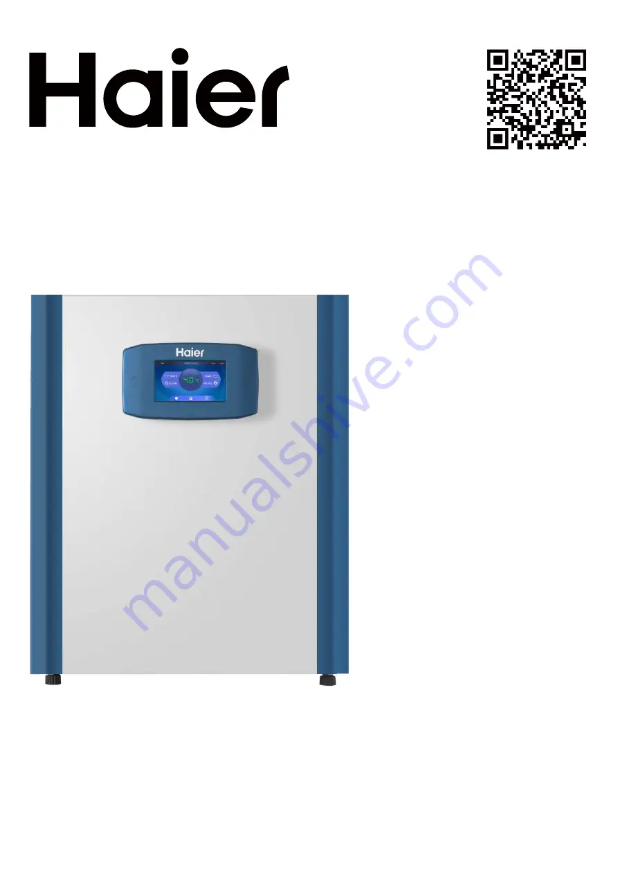
background image

Operation Instruction 
of CO

2

 Incubator

Model: 

HCP-80 

HCP-168 
HCP-258

• Please read this manual carefully before using the equipment. 
• The company reserves the right to  interpret the content of this manual. 
• Please keep it with your you for future reference. 
• Product technology or software is subject to upgrade without prior notice. 
• The image in this manual does not necessarily refl ect the product appearance of the actual product.

Summary of Contents for HCP-80

Page 1: ...sing the equipment The company reserves the right to interpret the content of this manual Please keep it with your you for future reference Product technology or software is subject to upgrade without prior notice The image in this manual does not necessarily reflect the product appearance of the actual product ...

Page 2: ...iption 5 Product lnstallation 7 Description of Parts Control Panel 11 Commissioning and application 13 Alarm 19 Cleaning and sterilization 20 CO2 concentration calibration 26 Periodic maintenance 28 Q A 29 Circuit diagram 30 Specification Packing List 31 ...

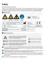
Page 3: ...ncubator to prevent potential electric shock or fire Be sure to place the incubator securely on solid and flat surface If the incubator is not secured firmly or the installation place is inappropriate the incubator may fall to cause damage or personal injury This product cannot be installed on combustible surface Safety Safety label Safety Precautions Check this manual in all cases marked with to le...

Page 4: ...y qualified service personnel are allowed to operate the incubator s intake pipe gas cylinder or system that stores CO2 with appropriate tools Be sure that the CO2 concentration in the workplace does not exceed the safety limit Release of large amount of CO2 into a closed indoor space may cause suffocation In the case of CO2 leakage take safety measures immediately Leave the room immediately and pre...

Page 5: ...ontainer with water or heavy objects on the incubator If the object falls it may cause personal injury or the spilled water may cause electric leakage or electric shock due to compromised insulation Do not ground the incubator through a gas pipe power hose telephone line or lightning rod The above grounding methods can cause electric shock or other dangers Do not touch any electrical parts such as...

Page 6: ... Pay attention to the calibration periods of the pressure reducing valve and pressure gauge 10 User prepared CO2 cylinders are pressurized vessels and must comply with relevant national regulations and management specifications for pressure vessels 11 Be sure to reserve certain clearance around the product with a clearance of no less than its right side dimension This space will easily cut off the p...

Page 7: ...tom of the working chamber adopts a water basin design you can directly inject water into the inner container by utilizing the inclined structure with high outer portion and low inner portion The temperature control circuit is controlled by a microcomputer and is equipped with functions such as automatic regulating characteristics and over temperature alarm The incubator adopts highprecision tempe...

Page 8: ... the incubator is filtered before penetrating into the chamber Dry heat sterilization at 180 Maintain the temperature of 180 for at least 1 5 hours The entire sterilization process takes only 12 hours from warming to cooling 8 Humanized design Friendly touch operated interface allows a sensitive response to finger movements with rubber gloves Announcement design paperless office message notepad funct...

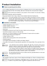
Page 9: ...r must have a space from the adjacent wall object as shown in the figure below The operation of the incubator requires CO2 gas flow Excessive CO2 can be harmful to health Therefore the installation position shall have good ventilation condition so that the exhaust gas from the rear wall can be quickly removed The incubator shall not be placed in a place without a ventilation system If there are sev...

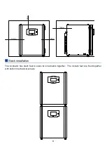
Page 10: ...8 The incubator has stack feet to stack two incubators together The 4 stack feet are fixed together with built in mechanical screws Stack installation 50mm 50mm 100mm 120mm ...

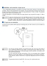
Page 11: ...gas source connection The corresponding interface is provided on the side of the electric cabinet on the back of the incubator There is hose supplied with the incubator The gas entering the incubator must first pass through the pressure reducing valve to reduce the output pressure to 1 0 Bar 0 2 Bar The pressure reducing valve needs to be provided by user From the perspective of technical safety th...

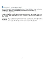
Page 12: ...nclude a power cable for grounding Plug the quick connector of the power cable into the lower right interface facing the incubator of the electric cabinet on the back of the incubator Make sure that the power cable is connected in place The power cable connector has a self locking structure The main power supply unit shall be well grounded Make sure that the power cable of the incubator is properl...

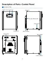
Page 13: ... Description of Parts Control Panel Power switch Stack foot CO2 high efficiency filter Electric cabinet Touch screen Horn Rotating foot Handle Description of Parts Sintered filter Remote alarm Cable connector ...

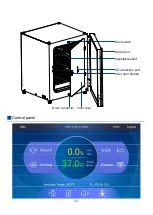
Page 14: ...12 Control panel Door switch Adjustable shelf Outer door CO2 detection port Inner door handle Drain connector Inner door ...

Page 15: ...the reading of the high pressure gauge and record the total C02 pressure in the high pressure cylinder Adjust the regulating screw clockwise to open the low pressure valve Rotate the pressure regulating screw of the low pressure gauge clockwise to compress to open the valve The high pressure gas at the inlet is depressurized The low pressure gas flow enters the working system through the outlet The...

Page 16: ...rface Network settings interface Time and temperature setting interface For all display interfaces the highlighted portion means that it is not selected Click on it and it will turn black which means that it is selected Caution ...

Page 17: ...er and operation curve of the working chamber during operation of the incubator 3 Setting Basic settings of the incubator 4 Level Water level display of the incubator white for normal and red for water shortage 5 Sterilization Click to enter the sterilization setting 6 Mute Click to clear the buzzing alarm the buzzing alarm continues when the set time is over 7 Message notepad and announcement Cli...

Page 18: ...nter the corresponding parameter settings interface Click the setting icon to enter the setting interface and then select the culture condition setting to enter the corresponding parameter setting The default setting temperature is 37 0 C and the CO2 concentration is 5 0 Home page Parameter settings ...

Page 19: ...utton on the home page if the alarm source still exist when the buzzing alarm delay time is over the buzzing alarm will continue Key volume It can be used to adjust the key volume Screen brightness It can be used to adjust the display brightness of the screen Screen sleep It is suggested to set the screen sleep time according to the service time so as to extend the touch screen s service life Lock...

Page 20: ...me page icon and the number of unread messages will be highlighted at upper right corner of the message box Notepad It is used for recording In normal mode the notepad is open for view by anyone In authorization mode the logged user can only see his her own records Announcement It is used for multiple users You can post the matters that you want to remind the other users to the home page When clic...

Page 21: ...w concentration alarm Internal CO2 concentration set concentration 0 5 or the set limit Display of parameter in red Pulse sound alarm Door opening alarm The door is opened for more than 30s Alarm flashes during the set alarm time Giving pulse sound alarm within the set alarm time Sensor fault Fault of the ambient temperature sensor Flicker alarm Pulse sound alarm Fault of the temperature sensor Fli...

Page 22: ...llution control process In the process of using the user needs to develop a corresponding pollution control process that is compatible with the incubator in accordance with the following requirements Wiping spraying disinfection Standard manual disinfection control procedures for the incubator and accessories Dry heat sterilization procedure The incubator can automatically operate the dry heat ste...

Page 23: ...sensor of the back CO2 concentration sensor Warning Disinfection with alcohol a The disinfectant of which the alcohol content is higher than 10 may form flammable and explosive gas mixture when mixing with air b Avoid using such disinfectants in open flame or high temperature environments during disinfection c Use such disinfectants in space with a good ventilation condition d After completion of di...

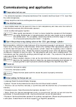
Page 24: ...upply and turn on the power switch 1 The user can enter the sterilization procedure in two ways Directly click the sterilization icon on the main interface to enter the sterilization procedure Click the setting icon to enter the setting interface and then click the sterilization icon to enter the sterilization procedure Warning Health hazard The surface of the working chamber may be contaminated C...

Page 25: ...rwise the water inside the incubator will evaporate under high temperature and then generate pressure while high temperature moisture is harmful to human body Caution The sterilization procedure cannot operate in the event of any of the following faults a Sensor damage b High actual value c Low actual value d Unreasonable actual value e Wrong communication f Water detected Warning Hot surface caut...

Page 26: ...he process of sterilization If the door is closed or the power is recovered a dialog window for sterilization appears on the screen to prompt the user for action to abort the process or to continue The temperature displayed in the dialog window is the real time temperature in the incubator b An alarm will also sound along with the sterilization pause warning dialog box Click any position on the sc...

Page 27: ...at sterilization is finished The user needs to manually press Finish to end the sterilization operation and then it will back to the main interface After finishing sterilization operate by following the steps below Open the outer door and inner door of the incubator Refill with water Install the HEPA filter if any Close all doors Sterilization stop interface ...

Page 28: ... a standard nitrogen and calibration kits from Haier or agencies designated by Haier Warning If the display screen shows that the CO2 concentration is greater than 0 5 after venting or opening the window for ten minutes turn off all CO2 gas supply devices in the room and perform air calibration again If the display screen shows that the CO2 concentration is still greater than 0 5 use nitrogen for a...

Page 29: ... concentration CO2 gas calibration kit supplied by the Haier or agencies designated by Haier Input the standard concentration input directly for saving Please refer to the kit instructions for the operation process 3 Restore default Restore the factory settings of the CO2 sensor ...

Page 30: ...ement period is 6 months The user can determine the replacement period according to the actual situation During normal use please check the vent line for air leakage at regular intervals if the gas consumption is large If any problem please inform Haier or agencies designated by Haier for maintenance and replacement During normal use please check the water level of the reservoir at regular interva...

Page 31: ...e the incubator by yourself Fault Troubleshooting The incubator does not work The power switch is ON and the cable is plugged in place Are the plug and the socket poorly connected Is the input power available The incubator does not heat Check the settings The incubator does not intake air Check if the air supply is connected Check if the pressure relief valve is opened Check the settings Large amo...

Page 32: ...CN29 CN31 5V GND B A 12V Display 5V GND B A 12V ambient temperature sensor Gas solenoid valve Door switch CO 2 sensor Door seal PT1000 1 PT1000 2 5V GND TXD RXD Fan CN9 24V GND 0 10 Over temperature protection CN17 CN15 CN25 CN26 CN11 CN13 CN24 CN7 CN1 CN3 CN42 CN40 CN23 CN10 CN6 CN8 Level relay ...

Page 33: ...uantity standard maximum 3 7 3 11 3 13 Structure Perforated adjustable Temperature parameter Temperature control range C Ambient temperature 3 55 Temperature fluctuation C 0 1 Temperature uniformity C 0 3 Type of temperature sensor PT1000 CO2 parameter CO2 control range 0 20 CO2 control error 0 1 Type of CO2 sensor IR Humidity Humidity control range 90 rh Noise 45 dB A 47 dB A 49 dB A Electrical pa...

Page 34: ...Packing List Name HCP 80 HCP 168 HCP 258 Shelf 3 3 3 Power cord 1 1 1 Drain pipe drain connector 1 1 1 Intake pipe 1 1 1 Intake pipe joint 1 1 1 Intake pipe clamp 2 2 2 User manual 1 1 1 Plastic bag 1 1 1 ...

Page 35: ...33 ...

Page 36: ...Checker ...

Reviews: