background image

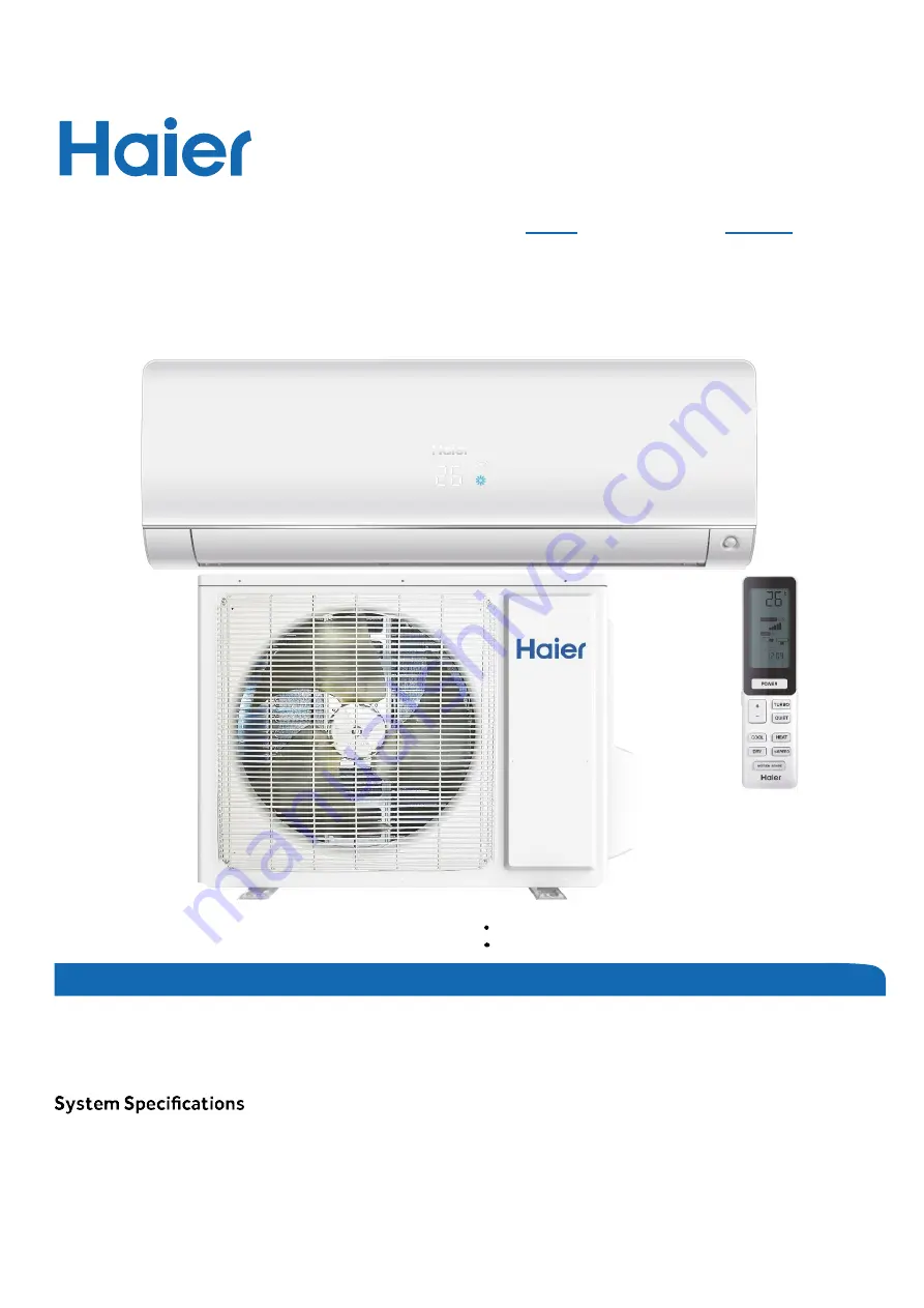
Ductless Split Heat Pump 

Service Manual

Design may vary b

y model number.

Please read this manual before installing this product. 

Keep this user manual for future reference.

PAGE 1

Safety Precautions/Introduction.................................................................................................3
Outdoor Unit Controls and Components ..................................................................................... 7
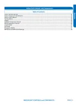
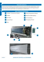
Indoor Unit Controls and Components ...................................................................................... 13

............................................................................................................. 27

Sequence of Operation ............................................................................................................. 19

Error Codes and Troubleshooting.............................................................................................. 28
Reference Information .............................................................................................................. 57

Table of Contents

Indoor
AW09EH2VHD
AW12EH2VHD
AW18EH2VHD

Outdoor
1U09EH2VHD
1U12EH2VHD
1U18EH2VHD

Summary of Contents for 1U09EH2VHD

Page 1: ... user manual for future reference PAGE 1 Safety Precautions Introduction 3 Outdoor Unit Controls and Components 7 Indoor Unit Controls and Components 13 27 Sequence of Operation 19 Error Codes and Troubleshooting 28 Reference Information 57 Table of Contents Indoor AW09EH2VHD AW12EH2VHD AW18EH2VHD Outdoor 1U09EH2VHD 1U12EH2VHD 1U18EH2VHD ...

Page 2: ... This page intentionally left blank ...

Page 3: ...INTRODUCTION PAGE 3 Introduction Safety Precautions 4 Warnings and Cautions 4 Introduction to System 5 5 SystemFundamentals 5 Table of Contents ...

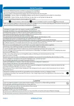
Page 4: ...Failure to follow any CAUTION may in some cases result in grave consequences ...

Page 5: ...to the system Always follow the manufacturer s installation instructions when installing a condensate pump maintained Improper clearances cause incorrect refrigerant pressures and coil freezing SystemFundamentals Theindoorunit will senseroom temperatureat thepoint wherethewallunit is installed Theindoorfanwill run continuously when placedinheatingorcooling mode roomtemperaturecould not besensedorm...

Page 6: ...PAGE 6 ...

Page 7: ... 8 8 Outdoor Main Control Boa rd 9 Terminal Block 10 Reactor 10 Compressor 10 Outdoor Fan Motor 10 Discharge Temperature Sensor 11 Defrost Temperature Sensor 11 Outdoor Ambient Temperature Sensor 11 Suction Line Temperature Sensor 11 4 Way Valve 12 Electronic Expansion Valve 12 Accumulator 12 Strainers 12 Base Pan Heater 12 ...

Page 8: ...s monitor key temperatures throughout the system to manage operational decisions 4 Way Valve Accumulator Compressor Defrost Temperature Sensor Discharge Temperature Sensor Electronic Expansion Valve Refrigerant Strainers Ambient Temperature Sensor Fan Motor Power Factor Reactor Suction Line Temperature Sensor Terminal Block Main Control Board PCB Module Control Board IPM Fan Blade 1 2 3 4 5 6 7 8 ...

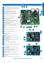
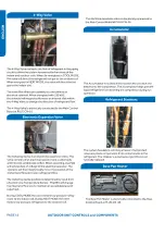
Page 9: ...5VDC and 15VDC pulsing communication connection between the PCB and the IPM ...

Page 10: ......

Page 11: ......

Page 12: ......

Page 13: ......

Page 14: ......

Page 15: ...Connector for coil temperature sensor and room temperature sensor ...

Page 16: ...display will indicate operating modes error codes indoor air temperature timer status and power status Ambient Temperature Sensor The Ambient room Temperature Sensor is a negative c thermistor that will decrease in resistance with increases in room air temperature The sensor is located on a clip mounted in the return air stream The sensor connects to the control board at Plug CN 6 Piping Temperatu...

Page 17: ......

Page 18: ... code B operation The wireless remote for the second unit is also set to code B J6 Selects room card able or disable Normally set to Set to when used in conjunction with a room card interface utilized in hotel rooms SW 1 and SW 2 Selects EEPROM codes 23 26 33 and 35 Set toidentify the tonnage of the unit Settings 9K 23 SW 9K 23 SW 9K 23 SW 1 OFF SW 2 OFF 3 OFF SW 4 OFF 3 OFF SW 4 OFF 3 OFF SW 4 OF...

Page 19: ......

Page 20: ...llowed by the outdoor fan The indoor unit fan willcontinue to run If the system detects a malfunction it may shut down or show an error code This code will be shown on the indoor di Indoor Unit To enter the cool mode point the infrared remote control at the indoor unit and press the power button then press the COOL mode button if not already setto cool mode The signals received by the infrared rec...

Page 21: ...tionsforautomaticcontrol areasfollows HighSpeed Tr Ts Medium Speed Ts T Ts 4 F LowSpeed Tr Ts 4 F When theindoorfanis runningin automaticmodewhenthe speedswitchesfrom hightolow the indoorfanwill maintain highspeed fora period of3minutes beforeswitchingtolow speed Four temperature sensors located in the outdoor unit provide temperature information to the outdoor unit main board for control of the s...

Page 22: ......

Page 23: ......

Page 24: ... f seconds anexhaust overheating protectionerrorcodewillbeindicatedat theoutdoorunit stop Decreasing the frequency rapidly 1HZ 1second TTC F F 212 F F F F Decreasing the frequency slowly 1HZ conds The frequency doesn t change Increasing the frequency 1HZ conds Increasing the frequency 1HZ 1second 2 Overheating Protection for Indoor Unit f f sensormonitorscoil temperaturein bothheating andcooling m...

Page 25: ... 1HZ 1 When Tpg_indoor begins T T to rise again and T T T Tpg3 the frequency of T T the compressor doesnot change When Tpg3 T T frequency of the compressor increases at the rate of 1HZ 10 second Example if 32 F sust ains for ains f ains f 2 minutes the outdoorunit will stop and indicate an underload malfunction code at the outdoor unit The com pressor stops for a minimum of 3 minutes When Min Tpg_...

Page 26: ...PAGE 32 ...

Page 27: ...e V Hz 208 230 60 1 208 230 60 1 208 230 60 1 Compressor Type DC Inverter Rotary DC Inverter Rotary DC Inverter Rotary Maximum Fuse Size A 15 20 30 Minimum Circuit Amp A 13 14 20 Outdoor Noise Level dB 55 55 51 Dimension Height in mm 27 1 2 697 27 1 2 697 30 762 Dimension Width in mm 35 890 35 890 36 1 4 920 Dimension Depth in mm 13 7 8 353 13 7 8 353 15 1 8 385 Weight Ship Net lbs kg 119 7 102 19...

Page 28: ...erature Sensor Failure F25 LED1 13 Flash Discharge Temperature Sensor Failure E1 LED1 No Flash Room Temperature Sensor Failure E2 LED1 No Flash Indoor Coil Temperature Sensor Failure 40 Error Code F6 LED1 12 Flash F7 LED1 11 Flash F21 LED1 10 Flash F25 LED1 13 Flash E1 LED1 No Flash E2 LED1 No Flash Wiring Diagram Reference 41 Error Code Indoor Outdoor F8 LED1 9 Flash Outdoor DC Fan Motor Fault 42...

Page 29: ...N8 CN9 4 AC L AC N at the IPM CN8 CN9 9K CN1 CN2 12K 18K 310 VDC available at 1 P N at the IPM CN1 CN5 9K CN8 CN9 12K 18K 2 P N at the PCB CN24 CN26 Module COM 5 G 15 VDC available at 1 CN23 at the PCB 2 CN11 at the IPM Module power 5 G 15 VDC available at 1 CN22 AT THE PCB 2 CN10 AT THE IPM 1 N and 3 C 0 80 2 L and 3 C 0 140 VAC Wiring Diagram Reference Conditions Needed for Basic Operation ERROR...

Page 30: ...l no more than a 2 deviation between There is a pulsing 0 to 80 VAC between terminal strip There is 230 VAC at terminals CN17 and CN21 There is 5 VDC at CN6 within 3 of the value listed Check This First Indoor Unit Models AW09EH2VHD AW12EH2VHD AW18EH2VHD ERROR CODES and Troubleshooting PAGE 30 ...

Page 31: ...Check This First Indoor Unit Wiring Diagram Reference Sensor Resistance Table PAGE 31 ERROR CODES and Troubleshooting ...

Page 32: ...M power module protection Complete the Check This First Flow Chart before continuing Models AW09EH2VHD AW12EH2VHD AW18EH2VHD 1U09EH2VHD 1U12EH2VHD 1U18EH2VHD Yes No No Yes Yes No Start Compressor runs for 10 min Normal operation PAGE 32 ERROR CODES and Troubleshooting ...

Page 33: ...Error Code F1 LED1 2 Flash Wiring Diagram Reference OUTDOOR UNIT WIRING DIAGRAM COMPRESSOR 0011509127 EEV Resistance Values EEV 6 pin 6 wire EEV 6 pin 5 wire ERROR CODES and Troubleshooting PAGE 33 ...

Page 34: ...x There is pulsing 50 200 from the terminal solder There is 264 373 VDC at Change set temperature Error Code Indoor Outdoor F2 LED1 24 Flash Overcurrent of the Compressor Complete the Check This First Flow Chart before continuing Models AW09EH2VHD AW12EH2VHD AW18EH2VHD 1U09EH2VHD 1U12EH2VHD 1U18EH2VHD ERROR CODES and Troubleshooting PAGE 34 ...

Page 35: ...OUTDOOR UNIT WIRING DIAGRAM COMPRESSOR 0011509127 Error Code F2 LED1 24 Flash Wiring Diagram Reference COMPRESSOR COMPRESSOR ERROR CODES and Troubleshooting PAGE 35 ...

Page 36: ...voltage CN11 on the IPM Yes Yes Yes No Yes No Yes No from building wiring harness power wiring harness COM Wiring Harness Line voltage at AC L OUT AC N OUT on the PCB Error Code Indoor Outdoor F3 LED1 4 Flash Communication Fault Between IPM and Outdoor PCB Complete the Check This First Flow Chart before continuing Models AW09EH2VHD AW12EH2VHD AW18EH2VHD 1U09EH2VHD 1U12EH2VHD 1U18EH2VHD ERROR CODES...

Page 37: ...OUTDOOR UNIT WIRING DIAGRAM COMPRESSOR 0011509127 Error Code F3 LED1 4 Flash Wiring Diagram Reference ERROR CODES and Troubleshooting PAGE 37 ...

Page 38: ...plate amount refrigerant Error Code Indoor Outdoor F4 LED1 8 Flash Overheat ProtectionForDischarge Temperature Complete the Check This First Flow Chart before continuing Models AW09EH2VHD AW12EH2VHD AW18EH2VHD 1U09EH2VHD 1U12EH2VHD 1U18EH2VHD ERR OR CODES and Troubleshooting PAGE 38 ...

Page 39: ...OUTDOOR UNIT WIRING DIAGRAM COMPRESSOR 0011509127 Error Code F4 LED1 8 Flash Wiring Diagram Reference EEV Resistance Values EEV 6 pin 6 wire EEV 6 pin 5 wire PAGE 39 ERROR CODES and Troubleshooting ...

Page 40: ...ED1 No Flash Room Temperature Sensor Failure E2 LED1 No Flash IndoorCoil Temperature Sensor Failure Complete the Check This First Flow Chart before continuing Models AW09EH2VHD AW12EH2VHD AW18EH2VHD 1U09EH2VHD 1U12EH2VHD 1U18EH2VHD Yes Yes Yes Yes No No No No Go to next step to test the board as well before sensor as well if previous step Re seat and Start wires for the faulting sensor Does See Re...

Page 41: ...M COMPRESSOR 0011509127 Sensor Resistance Table Error Code F6 LED1 12 Flash F7 LED1 11 Flash F21 LED1 10 Flash F25 LED1 13 Flash E1 LED1 No Flash E2 LED1 No Flash Wiring Diagram Reference PAGE 41 ERROR CODES and Troubleshooting ...

Page 42: ...DC voltage at fan motor plug CN21 between the Pin 6 BLUE and Pin 3 BLACK wire while spinning the fan motor No No No main board main board main board Measure DC voltage at fan motor plug CN21 between Pin 1 RED and Pin 3 BLACK Measure DC voltage at fan motor plug CN21 between Pin 4 WHITE and Pin 3 BLACK Measure DC voltage at fan motor plug CN21 between Pin 5 YELLOW and Pin 3 BLACK and subsequently l...

Page 43: ...OUTDOOR UNIT WIRING DIAGRAM COMPRESSOR 0011509127 Error Code F8 LED1 9 Flash Wiring Diagram Reference 1 3 4 5 6 1 3 4 5 6 1 3 4 5 6 1 3 4 5 6 PA GE 43 ERROR CODES and Troubleshooting ...

Page 44: ...stantially more than 5 VDC or 15 VDC pulsing at CN23 Yes Yes Yes Yes No No Error Code Indoor Outdoor F11 LED1 18 Flash Loss of Compressor Synchronization Complete the Check This First Flow Chart before continuing Models AW09EH2VHD AW12EH2VHD AW18EH2VHD 1U09EH2VHD 1U12EH2VHD 1U18EH2VHD PAGE 44 ERROR CODES and Troubleshooting ...

Page 45: ...OUTDOOR UNIT WIRING DIAGRAM COMPRESSOR 0011509127 Error Code F11 LED1 18 Flash Wiring Diagram Reference PAGE 45 ERROR CODES and Troubleshooting ...

Page 46: ...or Outdoor F12 LED1 1 Flash EEPROM Error Complete the Check This First Flow Chart before continuing Models AW09EH2VHD AW12EH2VHD AW18EH2VHD 1U09EH2VHD 1U12EH2VHD 1U18EH2VHD Wiring Diagram Reference OUTDOOR UNIT WIRING DIAGRAM COMPRESSOR 0011509127 PAGE46 ERROR CODES and Troubleshooting ...

Page 47: ... DCV at the motor There is DCV at the motor WH to BK 15VDC There is DCV at the motor There is DCV at the motor Error Code Indoor Outdoor E5 LED1 22 Flash Coil Frost Protection Complete the Check This First Flow Chart before continuing Models AW09EH2VHD AW12EH2VHD AW18EH2VHD 1U09EH2VHD 1U12EH2VHD 1U18EH2VHD PAGE 47 ERROR CODES and Troubleshooting ...

Page 48: ...Error Code E5 LED1 22 Flash Wiring Diagram Reference Sensor Resistance Table EEV Resistance Values EEV 6 pin 6 wire EEV 6 pin 5 wire PAGE 48 ERROR CODES and Troubleshooting ...

Page 49: ... is less than 5 VDC at CN22 module power and The voltage between Go to outdoor PCB No Yes Yes Yes Yes Yes Yes Yes No No Yes Yes No No No LED2 upper left is lighted fan motor at CN21 LED1 The display is Error Code Indoor Outdoor E7 LED1 15 Flash ID and OD Loss of Communication Complete the Check This First Flow Chart for both ID and OD units before continuing Models AW09EH2VHD AW12EH2VHD AW18EH2VHD...

Page 50: ...Error Code E7 LED1 15 Flash Wiring Diagram Reference PAGE 50 ERROR CODES and Troubleshooting ...

Page 51: ...OUTDOOR UNIT WIRING DIAGRAM COMPRESSOR 0011509127 Error Code E7 LED1 15 Flash Wiring Diagram Reference PAGE 51 ERROR CODES and Troubleshooting ...

Page 52: ...BLUE and Pin 4 BLACK wire while spinning the fan motor Measure DC voltage at fan motor plug CN9 between Pin 1 RED and Pin 4 BLACK Does it measure 300 380VDC Measure DC voltage at fan motor plug CN9 between Pin 5 WHITE and Pin 4 BLACK Does it measure between No No No Yes board motor Measure DC voltage at fan motor plug CN9 between Pin 6 YELLOW and Pin 4 BLACK Does it measure between Measure DC volt...

Page 53: ...Error Code E14 Wiring Diagram Reference 1 4 5 6 7 1 4 5 6 7 1 4 5 6 7 1 4 5 6 7 1 4 5 6 7 PAGE 5 3 ERROR CODES and Troubleshooting ...

Page 54: ... the temperature of the sensor being tested Step 3 Using an ohmmeter check the resistance value of the sensor Step 4 Referring to the temperature resistance table for the sensor being checked verify the resistance value corresponds to the temperature checked in Step 2 Replacethe sensor if thereading is open shorted or outside Step 5 Re seatthe plugon the connector at the conclusion of the test Che...

Page 55: ... Motor plug PCB for the test Failure to do so may provide inaccurate readings NOTE When using the test probes probe the back or side contacts of the plug to obtain the reading Do not try to probe the connector end of the plug as this may damage the contacts Checking the Indoor Unit Sensors NOTE Use respective temperature sensor chart for sensor Testing of the following components requires theuse o...

Page 56: ...bleshooting PAGE 56 Red Orange Yellow Pink Blue Red 296 5Ohm 295 5 Ohm 296 3 Ohm 296 1 Ohm Orange 594 5 Ohm 595 5 Ohm 594 5 Ohm Yellow 594 3 Ohm 594 5 Ohm Pink 594 3 Ohm Blue Step 3 Re seatthe plugon the PCB at the conclusion of the test Step 2 Referto the chart shown below for plug pin combinations and resistance values ERROR CODES and Troubleshooting ...

Page 57: ...PAGE 57 Ambient Defrost and Pipe Sensor Tables Discharge Sensor Tables ...

Page 58: ...eurs estdissipé 10VCC àl aided unvoltmètremanuel Le voyant LED2entreCN24etCN26doitêtre éteint 0011509127A OUTDOOR UNIT WIRING DIAGRAM COMPRESSOR Electrical ShockHazard Capacitorretainschargea er powerisdisconnected Con rm voltageatcapacitorhasdissipated 10VDC withhandheldvoltmeter beforeservicing LED2light betweenCN24andCN26shouldbe o RiesgodeDescargaEléctrica Elcapacitorre enecargaunavez desconec...

Page 59: ...8K model 33 code BM1 1 on 2 off WIRED CONTROLLER UP DOWN STEPMOTOR LEFT RIGHT STEMPMOTOR WIFI CN14 Notes Before replacing the board it is necessary to ensure that the machine is matched with the board code CN56 HUMAN SENSOR CN38 CN27 Y G GND 0011509128 WK B EVAPORATOR ELECTRIC CONTROL BOX COVER GND Y G RJ45 Diagnostic port CN5 CN1 CN2 SW1 OFF OFF OFF OFF CN3 CN4 Unit No SW1 DIP Switch position 1 2...

Page 60: ...4 45 8771 1 56 1 46 15 8 9 50 8956 47 1666 43 6714 1 54 1 44 17 6 8 48 3178 44 8454 41 5851 1 51 1 42 19 4 7 45 886 42 6525 39 6112 1 49 1 4 21 2 6 43 5912 40 58 37 7429 1 47 1 39 23 5 41 4249 38 6207 35 9739 1 45 1 37 24 8 4 39 3792 36 7676 34 2983 1 43 1 35 26 6 3 37 4465 35 0144 32 7108 1 41 1 33 28 4 2 35 6202 33 3552 31 2062 1 38 1 31 30 2 1 33 8936 31 7844 29 7796 1 36 1 29 32 0 32 2608 30 2...

Page 61: ...00 4 38 6 2437 5 9687 5 7007 1 21 1 18 102 2 39 6 017 5 7454 5 4812 1 25 1 22 104 40 5 7997 5 5316 5 2712 1 29 1 25 105 8 41 5 5914 5 3269 5 0704 1 33 1 29 107 6 42 5 3916 5 1308 4 8783 1 37 1 33 109 4 43 5 2001 4 943 4 6944 1 41 1 36 111 2 44 5 0163 4 763 4 5185 1 45 1 4 113 45 4 84 4 5905 4 35 1 49 1 44 114 8 46 4 6708 4 4252 4 1887 1 53 1 47 116 6 47 4 5083 4 2666 4 0342 1 57 1 51 118 4 48 4 35...

Page 62: ...2153 1 1066 3 32 3 06 186 8 86 1 2953 1 1794 1 073 3 38 3 1 188 6 87 1 2583 1 1448 1 0405 3 43 3 15 190 4 88 1 2226 1 1113 1 0092 3 48 3 19 192 2 89 1 188 1 0789 0 9789 3 53 3 24 194 90 1 1546 1 0476 0 9497 3 58 3 28 195 8 91 1 1223 1 0174 0 9215 3 64 3 33 197 6 92 1 091 0 9882 0 8942 3 69 3 37 199 4 93 1 0607 0 9599 0 8679 3 74 3 42 201 2 94 1 0314 0 9326 0 8424 3 8 3 46 203 95 1 003 0 9061 0 817...

Page 63: ...3028 84 0695 76 5017 1 76 1 62 2 19 87 2775 79 6222 72 5729 1 74 1 60 0 18 82 5577 75 4384 68 8710 1 72 1 59 1 17 78 1230 71 5010 65 3815 1 70 1 57 3 16 73 9543 67 7939 62 0907 1 68 1 55 5 15 70 0342 64 3023 58 9863 1 66 1 54 7 14 66 3463 61 0123 56 0565 1 64 1 52 9 13 62 8755 57 9110 53 2905 1 62 1 51 10 12 59 6076 54 9866 50 6781 1 60 1 49 12 11 56 5296 52 2278 48 2099 1 58 1 47 14 10 53 6294 49...

Page 64: ... 5974 9 2980 0 76 0 76 81 27 9 5129 9 2132 8 9148 0 80 0 80 82 28 9 1454 8 8465 8 5496 0 84 0 83 84 29 8 7942 8 4964 8 2013 0 87 0 86 86 30 8 4583 8 1621 7 8691 0 91 0 90 88 31 8 1371 7 8428 7 5522 0 95 0 93 90 32 7 8299 7 5377 7 2498 0 98 0 97 91 33 7 5359 7 2461 6 9611 1 02 1 00 93 34 7 2546 6 9673 6 6854 1 06 1 04 95 35 6 9852 6 7008 6 4222 1 10 1 07 97 36 6 7273 6 4459 6 1707 1 13 1 11 99 37 6...

Page 65: ...7 75 1 7974 1 6533 1 5194 2 83 2 63 169 76 1 7434 1 6021 1 4710 2 88 2 67 171 77 1 6913 1 5528 1 4243 2 92 2 71 172 78 1 6409 1 5051 1 3794 2 97 2 75 174 79 1 5923 1 4592 1 3360 3 02 2 80 176 80 1 5454 1 4149 1 2942 3 07 2 84 178 81 1 5000 1 3721 1 2540 3 12 2 88 180 82 1 4562 1 3308 1 2151 3 17 2 93 181 83 1 4139 1 2910 1 1776 3 22 2 97 183 84 1 3730 1 2525 1 1415 3 27 3 01 185 85 1 3335 1 2153 1...

Page 66: ... 10531 3695 8700 6388 2 93 2 44 16 6 27 11885 1336 9847 724 8152 2338 2 92 2 43 14 8 26 11096 6531 9212 8101 7641 8972 2 91 2 42 13 25 10365 4565 8622 8491 7166 7474 2 9 2 42 11 2 24 9687 027 8074 3787 6724 1389 2 88 2 41 9 4 23 9057 2314 7564 2244 6311 6413 2 87 2 41 7 6 22 8472 2852 7089 4741 5927 0206 2 86 2 4 5 8 21 7928 7217 6647 4547 5568 2222 2 84 2 39 4 20 7423 3626 6235 7109 5233 3554 2 8...

Page 67: ...3 62 6 17 850 6086 761 0603 680 3265 2 24 2 02 64 4 18 807 3024 723 4134 647 658 2 22 2 66 2 19 766 4212 687 8205 616 7252 2 2 1 99 68 20 727 8172 654 1596 587 4271 2 18 1 98 69 8 21 691 3524 622 3161 559 6694 2 16 1 96 71 6 22 656 8979 592 1831 533 3634 2 14 1 95 73 4 23 624 3328 563 6604 508 4261 2 12 1 93 75 2 24 593 5446 536 654 484 7796 2 1 1 92 77 25 564 4275 511 076 462 351 2 09 1 9 78 8 26...

Page 68: ... 89 0211 85 0614 81 2048 1 18 1 15 152 6 67 85 4976 81 7908 78 1744 1 15 1 12 154 4 68 82 1303 78 6615 75 2715 1 13 1 1 156 2 69 78 9116 75 6668 72 4902 1 1 1 08 158 70 75 8343 72 8004 69 8249 1 08 1 06 159 8 71 72 8916 70 0561 67 2703 1 05 1 03 161 6 72 70 077 67 4283 64 8213 1 03 1 01 163 4 73 67 3844 64 9115 62 4731 1 0 99 165 2 74 64 808 62 5006 60 2211 0 98 0 96 167 75 62 3423 60 1906 58 0609...

Page 69: ...4 8577 2 15 2 04 239 115 16 401 15 3696 14 3902 2 19 2 08 240 8 116 15 9167 14 902 13 9394 2 23 2 12 242 6 117 15 4489 14 4506 13 5047 2 27 2 16 244 4 118 14 9968 14 0149 13 0855 2 32 2 19 246 2 119 14 5599 13 5942 12 6811 2 36 2 23 248 120 14 1376 13 1879 12 2909 2 41 2 27 249 8 121 13 7294 12 7955 11 9144 2 45 2 31 251 6 122 13 3347 12 4165 11 551 2 5 2 35 253 4 123 12 9531 12 0503 11 2003 2 54 ...

Page 70: ...ww w Haier com Haier America Wayne NJ 07470 2020Haier America Trading LLC Issued Date November 2020 Model AW09EH2VHD 1U09EH2VHD AW12EH2VHD 1U12EH2VHD AW18EH2VHD 1U18EH2VHD ...

Reviews: