

1059037A • February 2007
Copyright © 2007, GE Security Inc.
SmartCom Door Station
Installation Instructions
Introduction
This is the GE
SmartCom Door Station Installation Instructions
for model CC-SCDOR1.
SmartCom provides a modular, expandable system for the distri-
bution of music and intercom functions throughout the home.
Up to two door stations can be added per system. The door
station includes a weather-resistant speaker, a sensitive micro-
phone, and a door bell call button (
). When you press the
door bell call button, it initiates a door bell sound in the intercom
system. When the intercom room station answers, you can talk
back
hands free
at the door station.
Figure 1. Door station
Prewire requirements
You will need to have a prewired, preinstalled single-gang box.
Required equipment
You will need the following equipment to install the door station:
• Punchdown tool or EZ RJ45 ratchet-style crimper
• Screwdriver
Installation
Door stations can only be connected to the first (Master)
intercom hub. Refer to your intercom hub documentation for
details.
To connect the door station to the intercom hub, see
and
do the following:
1.
Connect one end of a CAT 5 cable to the back of the door
station using one of the following connections:
• RJ45 jack with both of the ends of the cable wired the
same, 568A standard (see
• The 110-style punchdown block (follow the wiring
color code in
).
2.
Connect the other end of the CAT 5 cable to the front of the
intecom hub in the Door 1 or Door 2 RJ45 jack Be sure the
RJ45 on the intercom hub end is wired per 568A standard.
Note:
We do not recommend using the RJ45 jack for harsh
environments, wet or extremely humid locations. Use the
punchdown block for the most reliable connection. Use the
correct 110 punchdown tool and follow 568A wiring
standard.
3.
Set the speaker volume as desired by adjusting the volume
level pot on the back of the door station.
4.
Mount the door station in a single-gang box using the
screws provided.
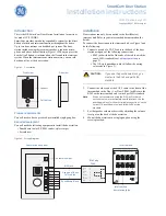
Figure 2. Wiring diagram
Call button
Side view
Front view
Speaker
CAUTION:
If you use the punchdown block, you
must wire the RJ45 end per 568A
standard.
568A
Volume
Intercom Room Stations
1 2 3 4
5 6 7 8
Door Door Exp Audio
1 2 hub hub
Power
12VDC
1 Amp
W/G
G
W/O
BL
W/BL
O
W/BR
BR
1
2
3
4
5
6
7
8
W/BL
BL
W/O
O
W/G
G
W/BR
BR
Door station back view
Intercom hub
RJ45 plug
568A
Use one of these
RJ45 jack
Punchdown block
CAT5 cables
568A
Intercom hub
door station jacks
Volume level pot


