1051855A
December 2004
RCR-PET Lens Replacement Kit
Installation Instructions
Description
This is the RCR-PET lens replacement kit to update your Preci-
sionLine RCR-PET Motion Sensor. The kit includes:
• one RCR-PET lens
• one black plastic lens shield
Installation
To replace the lens in the unit, do the following:
1.
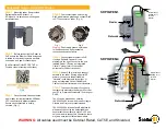
Use a small flathead screwdriver to pry the nameplate off
the cover (
). Loosen the cover mounting screw and
pull the cover off the base.
Figure 1.
Exploded view
2.
Use a #4 Phillips screwdriver to remove the two circuit
board mounting screws (
). Slide the circuit board
out of the mounting guides and lift the circuit board off the
front cover.
Figure 2.
Removing the circuit board
3.
To remove the white plastic lens shield (
), press
down on the shield release tab and slide the shield out of the
shield guides. Discard the shield.
Figure 3.
Removing the lens shield
4.
Slide the RCR-PET lens out of the guides (
the lens off the mounting pins. Discard the lens.
Figure 4.
Removing the lens
5.
Place the new lens under the guides (
) and over the
mounting pins.
6.
Slide the new black plastic shield under the shield release
tab (
). Align the shield over the mounting pins, and
snap the shield down.
7.
Slide the circuit board under the mounting guides (
and replace the two mounting screws.
Do not overtighten
the mounting screws
.
8.
To reattach the cover on the base, place the tabs at the
bottom of the cover over the guides at the bottom of the base
and align the connection block pins over the connection
block (
). Gently snap the unit together.
9.
Insert the mounting screw and reattach the nameplate
(
10. The multicolor LED located on the bottom of the unit
(
) should light green for approximately 25 seconds
then go out.
11. Walk through the intended coverage area to walk test the
unit. The LED color (
) indicates the status of the
unit as described in
. Thirty minutes after you reat-
tach the cover on the base, the LED will only indicate an
alarm condition.
CAUTION
CAUTION
You must be free of all static electricity before
handling sensor circuit boards. Touch a
grounded surface or wear a grounding strap
before touching circuit boards.
Nameplate
Mounting screw
Cover
Base
LED
Mounting screw
Mounting screw
Guide
Guide
Circuit board
Release tab
Guide
Guide
Guide
Shield
Guide
Guide
Lens


