


www.GEAppliances.com
49-7406 11-00 JR
Operating Instructions
Auto Changeover . . . . . . . . . .10
Day/Time Setting Mode . . . . .6
Default Mode . . . . . . . . . . . . . . .4
Fan Control . . . . . . . . . . . . . . .10
Hold and Temporary
Override . . . . . . . . . . . . . . . . . . .6
Initial Power Up . . . . . . . . . . . . .3
LCD Backlight . . . . . . . . . . . . .10
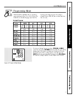
Programming Mode . . . . . . .7–9
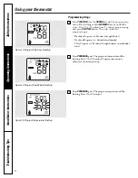
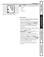
Reviewing and Changing
Setpoint Temperature . . . . . . .5
Selecting Temperature Scale . .4
Thermostat Overview . . . . . .2–3
Time Format . . . . . . . . . . . . . . .5
Verification . . . . . . . . . . . . . . .10
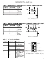
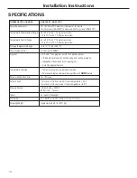
Installation Instructions
Location . . . . . . . . . . . . . . . . . . 11
Mounting and Wiring . . . 11–13
Specifications . . . . . . . . . . . . . .14
Tools Required . . . . . . . . . . . . 11
Troubleshooting Tips
. . . . . 15
Customer Service
Warranty . . . . . . . . . . . . . . . . . 20
Write the model and serial
numbers here:
#
#
You can find them on a label on
the thermostat.
RAK147P1
RAK163P1
Owner’s Manual &
Installation Instructions
Therm
osta
ts
Digital Programmable


