


31-5000463 Rev. 0 11-19 GEA
RAB26A
Room Air Conditioner
Wall Sleeve for AJ Series
Built-In Models
Before you begin - Read these instructions completely
and carefully. IMPORTANT – OBSERVE ALL
GOVERNING CODES AND ORDINANCES. Note to
Installer – Be sure to leave these instructions with the
Consumer. Note to Consumer – Keep these instructions
with your Owner’s Manual for future reference.
NOTE: Handle the wall sleeve carefully.
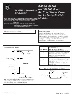
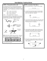
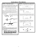
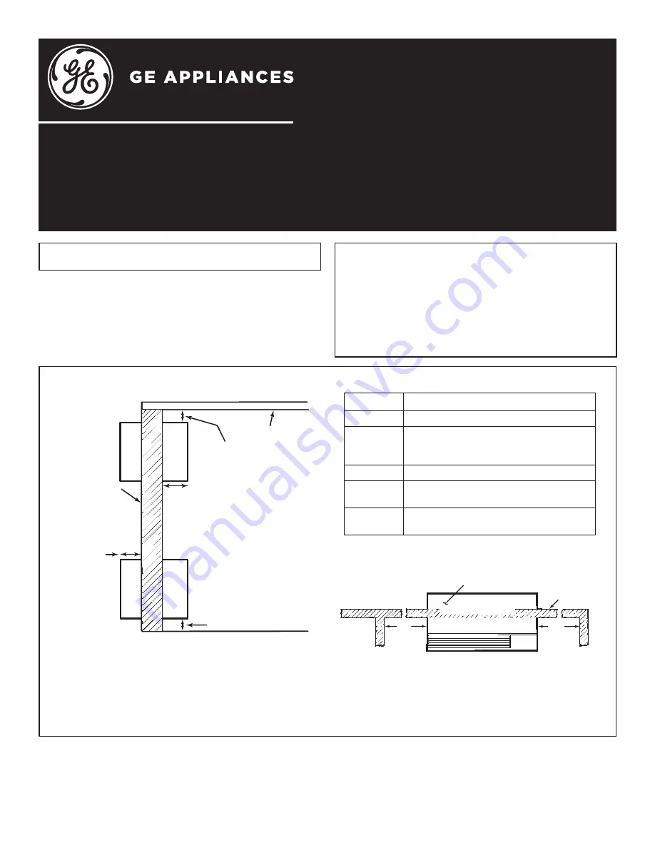
CRITICAL DIMENSIONS
Ceiling
“A”
“B”
“C”
Roomside
Outside wall
“D”
)LQLVKHGÀRRURUWRSRIFDUSHW
NOTE:
Care should be taken in location of electrical
supply entry in relationship to wall sleeve to ensure
access to power once the unit is installed.
Dimensions Recommended Installation Clearance
A
7RSRIZDOOVOHHYHWR¿QLVKHGFHLOLQJ´PLQ
B
3URMHFWLRQRIZDOOVOHHYHLQWRURRP´PLQ
,IPRUHWKDQ´RIZDOOVOHHYHSURMHFWVLQWR
the room, other support is recommended
C
3URMHFWLRQRIZDOOVOHHYHWRRXWVLGH´PLQ
D
+HLJKWDERYH¿QLVKHGÀRRURUWRSRI
FDUSHW´PLQ
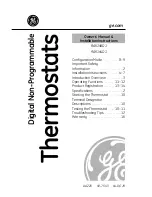
E
/HIW5LJKWVLGHRIZDOOVOHHYHWRDGMDFHQW
ZDOO´PLQ
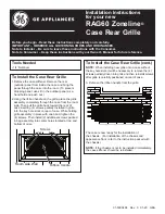
INSTALL WALL SLEEVE LEVEL FROM SIDE TO SIDE
AND WITH A SLIGHT TILT FROM FRONT TO REAR
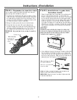
NOTE: If an internal drain is to be used, install the
wall sleeve level from side to side and level from
front to rear.
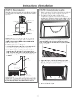
WALL SLEEVE LOCATION
$VDJHQHUDOUXOHWKHDLUFRQGLWLRQHUVKRXOG
be located in an outside wall to ensure proper
distribution of conditioned air. It should be located
in a portion of the wall where there is no electrical
ZLULQJRUSOXPELQJDQGZKHUHWKHUHDUHQR
obstructions immediately inside or outside.
Outside wall
“E”
“E”
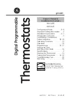
Top of case
Top of wall sleeve