Installation instructions
for your new
RAB-71 Standard
or Extended Room
Air Conditioner Case
Before you begin—Read these instructions completely and carefully.
IMPORTANT—OBSERVE ALL GOVERNING CODES AND ORDINANCES.
Note to Installer—Be sure to leave these instructions with the Consumer.
Note to Consumer—Keep these instructions with your Use and Care Book for future reference.
1
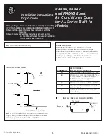
Critical Dimensions
Note:
Care should be taken in location of electrical supply
entry in relationship to wall sleeve to assure access
to power once the unit is installed.
Ceiling
“A”
“B”
“C”
Roomside
Outside wall
“D”
Finished floor or top of carpet
Recommended
Dimensions
Installation Clearance
A
Top of case to finished
ceiling – 3
″
min.
B
Projection of case into
room – 0
″
min. (no sub-base)
2
3
⁄
8
″
min. when
sub-base is used.
If more than 6
″
of the case
projects into the room, a
sub-base or other support
is recommended.
C
Projection of case to
outside – 1/4
″
min.
D
Height above finished floor or top
of carpet – 0
″
min. without sub-base
3
″
min. with sub-base
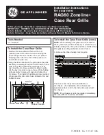
E
Left/Right side of case to
adjacent wall – 2
″
min.
Top of case
Outside wall
“E”
“E”
Pub. No. 30-7795-2
04-00 JR
INSTALL CASE LEVEL IN ALL DIRECTIONS
Note:
•
Handle the case carefully.
•
The cardboard stiffener inside the case, and the rear
protective panel must remain in place until the chassis
is installed to assure case rigidity and squareness.
•
If a sub-base is to be used, it may be desirable to
assemble it to the case before securing the case in
the wall.
Case location
As a general rule the air conditioner should be
located in an outside wall to assure proper
distribution of conditioned air. It should be located
in a portion of the wall where there is no electrical
wiring or plumbing, and where there are no
obstructions immediately inside or outside.