


Reviews:
No comments
Related manuals for NEMA
Go
Brand: ZAPTEC Pages: 240
eMH1 WALLBOX
Brand: ABL Pages: 94
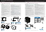
eMH1 WALLBOX
Brand: ABL Pages: 176
Green Motion Building
Brand: Eaton Pages: 12

LS4 Wallmounted
Brand: GARO Pages: 15
ENTITY PRO
Brand: GARO Pages: 2
DAF POWERCHOICE 250A
Brand: Paccar Pages: 20
SPI6
Brand: Schumacher Electric Pages: 87
eMH3
Brand: ABL Pages: 66
eMH3
Brand: ABL Pages: 4
SmartShot Automatic 12V 1.5 Amp 5 Stage
Brand: Yuasa Pages: 44
Green Motion DC 66
Brand: Eaton Pages: 18
241170-53-1
Brand: Inbay Pages: 20
DAF CHARGEMAX 90
Brand: Paccar Pages: 40
13553
Brand: Gacell Pages: 12
Wallbox GLB
Brand: GARO Pages: 15
PACCHARGE AC20
Brand: Paccar Pages: 63
F-2024
Brand: Ferve Pages: 28


