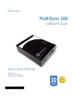
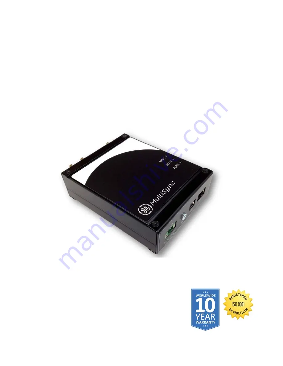
background image

GE

Digital Energy

MultiSync 100

1588 GPS Clock

1601-0300-A1

Instruction Manual

Revision: 1.0x
Manual P/N: 1601-0300-A1
Manual Order Code: GEK-119628

Summary of Contents for MultiSync 100

Page 1: ...GE Digital Energy MultiSync 100 1588 GPS Clock 1601 0300 A1 Instruction Manual Revision 1 0x Manual P N 1601 0300 A1 Manual Order Code GEK 119628 ...

Page 2: ...ns abnormally proceed with caution Otherwise the protection provided by the equipment may be impaired and can result in Impaired operation and injury Caution Hazardous voltages can cause shock burns or death Installation service personnel must be familiar with general device test practices electrical awareness and safety precautions must be followed Before performing visual inspections tests or pe...

Page 3: ...voided could result in minor or moderate injury Indicates practices not related to personal injury For further assistance For product support contact the information and call center as follows GE Digital Energy 650 Markland Street Markham Ontario Canada L6C 0M1 Worldwide telephone 1 905 927 7070 Europe Middle East Africa telephone 34 94 485 88 54 North America toll free 1 800 547 8629 Fax 1 905 92...

Page 4: ......

Page 5: ...ifications 4 Antenna requirements 4 Testing and certification 5 2 THEORY OF OPERATION GPS and precise time synchronization 7 The IRIG B Time Code Standard 8 Modulated IRIG B 9 Unmodulated IRIG B 9 IEEE 1344 Extensions 10 Defining IRIG B Time Codes 10 IRIG B in the MultiSync 100 1588 GPS Clock 11 IRIG B wiring considerations 12 Network Time Protocol Simple Network Time Protocol 12 SNTP 12 NTP SNTP ...

Page 6: ... Configure I O settings 29 Configure output port settings 30 Set output sync reporting 31 Enable relay alarms 32 Configure network settings 33 Change basic network settings 33 Change NTP settings 35 Change IEEE 1588 C37 238 PTP settings 36 Change SNMP settings 37 Set notifications 38 Configure maintenance settings 39 Apply maintenance overrides 39 Set software login banner 40 Reset the MultiSync 1...

Page 7: ...ation options include adjustable hold over times in cases of poor GPS coverage and compensation for installation parameters such as antenna cable length Features Features of the MultiSync 100 include DC IRIG B Unmodulated DCLS C37 118 User defined pulses Modified Manchester NTP SNTP IEC 61850 IEEE 1588 2011 Supports Power Profile C37 238 SNMP v1 v2c v3 DCF 77 Isolated power supply HIgh power line ...

Page 8: ... µs over 5 hours 7 ppb Electrical POWER SUPPLY Voltage 36 to 300 VDC Power drain 5 W max ISOLATION Power to antenna 3 75 kV Power to I O 3 75 kV INPUTS RJ45 UTP connector 10 100 Mbps USB2 0 Type B OUTPUTS Sync indication output 200 V 150 mA max 2 x TTL outputs Time codes or pulses or user defined Electrical specification TTL CMOS compatible 0 5 V 150 mA sink source Timing accuracy 100 ns to UTC Mu...

Page 9: ...se used by PTP Alternate Time Offset TLV support with automatic or manual offset SNMP MIB support C37 238 NTP General Stratum 1 NTP SNTP time server Multicast Broadcast server capability Optional MD5 authentication SNMP General V1 V2C and V3 support independently enabled Configurable V1 and V2C community names and security groups Fully configurable via SNMP V3 User based Security Module USM suppor...

Page 10: ...CHANICAL PROPERTIES Dimensions H W D 45 110 155 mm Weight 0 42 kg Installation Metal DIN rail mountable case with IP30 Ingress Protection rating Mechanical specifications Antenna requirements ANTENNA PORT SPECIFICATIONS Voltage 5 VDC Current 100 mA max Input impedance 50 Ω Total gain The total combined gain of the antenna system antenna cable and connectors should fall in the range of 10 to 35 dB ...

Page 11: ...C Power port 4 kV 4 IEC 61000 4 5 Surge Signal Ports 4kV line to earth 2kV line to line 4 D C Power Ports 2kV line to earth 1kV line to line 3 IEC 61000 4 6 Induced RFI Signal Ports 10 V 3 D C Power ports 10 V 3 Earth Ground Ports 10 V 3 IEC 61000 4 8 Magnetic Field Enclosure Ports 40 A m continuous 1000A m for 1s IEC 61000 4 29 IEC 61000 4 11 Voltage Dips and Interrupts D C Power ports 30 for 0 1...

Page 12: ... C Power Ports 4 kV IEEE 37 90 1 Oscillatory Signal Ports 2 5kV common mode 1MHz D C Power ports 2 5 kV common 1 kV diff mode 1MHz IEEE 37 90 H V Impulse Signal Ports 5 kV fail safe relay output D C Power ports 5 kV IEEE 37 90 Dielectric Strength Signal Ports 2 kVAC D C Power ports 2 kVAC Test Description Test Levels IEC 60068 2 1 Cold Temperature Test Ad 40 C 16 hours IEC 60068 2 2 Dry Heat Test ...

Page 13: ...urement of duration between events Coordinated Universal Time UTC a time system adopted in 1972 UTC is based on the weighted combination of atomic clocks located around the world UTC occasionally changes by the addition of leap seconds Frequency the measure of the number of events that occur within a time interval such as the number of oscillations of a voltage waveform within one second Power sys...

Page 14: ...elationship between the receiver clock and GPS time is established time signals can be produced by the receiver Synchronization between receivers at different locations can be established and maintained using GPS time If time signals are required to maintain synchronization with UTC the UTC correction in the navigation message can be applied and time signals such as one pulse per second 1PPS signa...

Page 15: ...s of communicating analog pulses IRIG Standard 200 04 Modulated IRIG B A modulated IRIG B clock continuously produces a sine wave signal with the amplitude of the signal modulated to indicate the value of a specific bit The length of the modulation determines a logical 0 logical 1 or position identifier Modulated or amplitude modulated AM IRIG B is the original method for distributing IRIG B time ...

Page 16: ... was revised in 2004 to include year data The 200 04 Standard allows IRIG B to publish BCDYEAR as described The IEEE 1344 Standard has been replaced by C37 118 2005 IEEE Standard for Synchrophasors for Power Systems although the term IEEE 1344 extensions is still in common use The term C37 118 extensions may be used instead Defining IRIG B Time Codes The IRIG Standard further defines the Time Code...

Page 17: ...BCDYEAR in the time code On the GE Configuration tool I O tab Under IRIG B Pulse Output Port select IRIG B and set Modulation to DCLS Under IRIG B Stream set Extensions to C37 118 and leave Binary code in seconds unchecked B007 DC Level Shift BCDTOY BCDYEAR and SBS in the time code On the GE Configuration tool I O tab Under IRIG B Pulse Output Port select IRIG B and set Modulation to DCLS Under IR...

Page 18: ...s are normally connected in parallel to the clock output port Solving the resulting equivalent circuit will determine if the clock has enough capacity to drive the connected devices and if the voltage level at each device is sufficient for operation The MultiSync 100 clock output ports are rated for 0 5V and 150mA sink source Network Time Protocol Simple Network Time Protocol Network Time Protocol...

Page 19: ...Operation of the IEEE 1588 protocol relies on a measurement of the communication path delay between the time source referred to as a master and the receiver referred to as a slave This process involves a message transaction between the master and slave where the precise moments of transmit and receive are measured preferably at the hardware level Messages containing current time information are ad...

Page 20: ... and Atomic clocks are stratum 1 the clock identifier accuracy of the clock s time base the stability of the local oscillator and the closest clock to the grand master based on the spanning tree algorithm The algorithm was designed so that no negotiation has to occur between clocks while ensuring that configurations with two masters no masters or an oscillation between masters never occur BMC allo...

Page 21: ...ary clocks are the most common device within a PTP network They are generally used as the end nodes within a network as part of the devices needing synchronization Ordinary clocks can come in various forms and with various interfaces to external devices At the device end they re typically a slave clock only Boundary Clock Boundary clocks are used within a PTP system to sit in place of standard net...

Page 22: ...ations This profile is based on the specific substation network architectures data exchange mechanisms and performance of time distribution service required for power system applications The profile is optimized for isolated Ethernet networks and a small number of dedicated grandmaster capable clocks typical of the power substation environment The Power Profile achieves the above goals by strictly...

Page 23: ...MANUAL 17 Figure 4 Typical MultiSync 100 GPS Clock application MultiSync 100 1588 GPS Clock GPS Antenna ETH P2 P1 Universal Relays v 7 w 1588 Universal Relays v 7 w 1588 8 Series w 1588 1588 MultiLink 3000 3100 with 1588 Modules 1588 1588 1588 IRIG B GPS Satellite System RG59 coaxial cable ...

Page 24: ...5 Timing accuracy for Synchrophasors MultiSync 100 1588 GPS Clock ETH P2 P1 IRIG B N60 Network Stability and Phasor Measurement v 7 1588 1588 N60 Network Stability and Phasor Measurement v 7 100 nanosecond accuracy for synchrophasor applications over IRIG B or 1588 C37 238 GPS Antenna GPS Satellite System ...

Page 25: ...MULTISYNC 100 GPS CLOCK INSTRUCTION MANUAL 19 MultiSync 100 GPS Clock Chapter 3 Installation Installation This chapter outlines installation of hardware and software Device hardware Front panel ...

Page 26: ...ect to the antenna 4 Connect the MultiSync 100 to the network switch 5 Connect to power ensuring the correct DC voltage 36V 300V is used 6 Connect the Sync indication relay to the alarm circuit if required C Common NO Normally Open NC Normally Closed 7 Once the MultiSync 100 is installed and configured connect the clock outputs to your devices An RG59 cable or similar with characteristic impedance...

Page 27: ...LOCK INSTRUCTION MANUAL 21 Install GE Configuration Tool software To install the software 1 Insert the accompanying CD into the CD ROM drive of any PC connected to the same network as the MultiSync 100 2 Select the MultiSync GE Configuration Tool from the List of available software ...

Page 28: ...22 MULTISYNC 100 GPS CLOCK INSTRUCTION MANUAL INSTALL GE CONFIGURATION TOOL SOFTWARE CHAPTER 3 INSTALLATION ...

Page 29: ...ndicators The front panel of the MultiSync 100 contains three LEDs GE Clock Configuration Tool software interface The MultiSync 100 can be configured by running the GE Clock Configuration Tool software on any PC connected to the same network as the MultiSync 100 Before starting the GE Clock Configuration Tool software check that you have the following Administrative rights on your PC UDP exception...

Page 30: ... login for the GE Clock Configuration Tool is User Name admin Password Password NOTE If the MultiSync 100 does not appear when you press Discover in the GE Clock Configuration Tool either connect the MultiSync 100 directly using a cross over Ethernet cable or install the driver from the CD and connect the MultiSync 100 using a USB cable 3 Set a new password as prompted or by clicking the Security ...

Page 31: ...ect the port from the I O Ports list 5 2 Set the IRIG B Pulse Output Port type to IRIG B 5 3 For both IRIG B Streams A and B change the Extensions to C37 118 to include the year in the IRIG B data 6 If using IEEE 1588 C37 238 click the PTP tab and check Enable if not already checked Configuration changes may be required for your network 7 Click the Update icon at the top of the GE Config window to...

Page 32: ...e hold and drag down the Open icon to access the Load with Network icon 2 Browse to the configuration file to open and click OK 3 Click the Update icon at the top of the GE Config window to save the configuration loaded from the file to the clock Top menu buttons Reload Reload configuration from the active clock Any configuration changes made are lost Update Save configuration to the active clock ...

Page 33: ...atellite determined Coordinated Universal Time UTC configured Local Daylight Time LDT daylights savings settings and general system information NOTE The clock displays can be customized by clicking each clock to toggle between analog 12 hour digital and 24 hour digital displays Use the Clock tab to set the LDT and regional daylight savings time ...

Page 34: ...aining multiple regions with different daylight savings conventions have more than one entry 4 Click OK to enter the selected time zone and regional daylight savings settings To enter custom daylight savings settings change individual settings within the Localization area of the Clock tab NOTE To disable daylight savings time ensure that the Region observes daylight savings tick box is not selecte...

Page 35: ...OCK INSTRUCTION MANUAL 29 Configure I O settings The I O tab displays the configured output pulse and output port settings as well as the current status of all available relay alarms Use the I O tab to set output pulses and output formats and to enable relay alarms ...

Page 36: ...rom the drop down list User defined pulse user configured time code DCF 77 simulation time code compliant with the DCF 77 specification IRIG B time code compliant with the IRIG B specification 4 For a user defined pulse set the frequency offset and duration 5 For a DCF 77 compliant time code check the box to use UTC Time for the time code 6 For an IRIG B compliant time code NOTE Two different IRIG...

Page 37: ...ck the radio buttons to choose between Outputs report the sync state and Outputs always report in sync NOTE The selected sync reports apply to output from both ports 2 1 If Outputs report the sync state is selected you can check the box to suppress sync reporting when out of sync 2 2 If Outputs always report in sync is selected you can check the box to always report that the sync relay is on suppr...

Page 38: ...to select the RELAY ALARM Output port All available alarms are listed 3 In the Alarms area check or uncheck boxes to enable or disable specific alarms Low Satellites Triggers when no satellites have sufficient signal strength to be used for GPS synchronization Holdover Triggers when the MultiSync 100 has lost sync with GPS PTP or NTP after being in sync over 2 minutes The Holdover alarm is active ...

Page 39: ...k settings The Network tab displays information about the current network connection Use the Network tab to change network settings as needed for your specific network configuration and to configure notifications Change basic network settings 1 Click the Network tab in the GE Config window 2 Click the Basic tab ...

Page 40: ...hange VLAN settings check the Enable box in the VLAN area 4 To change Ethernet Link settings check the Advanced Options box in the top right corner of the Network tab 5 Change settings as needed When finished click the Update icon at the top of the GE Config window to save the changed configuration to the clock ...

Page 41: ... INSTRUCTION MANUAL 35 Change NTP settings 1 Click the Network tab in the GE Config window 2 Click the NTP tab and check Enable if not already checked 3 To enable MD5 check Enable in the MD5 Authentication area MD5 authentication keys may be viewed or changed when enabled ...

Page 42: ...nt SNTP radio button 5 Change settings as needed When finished click the Update icon at the top of the GE Config window to save the changed configuration to the clock Change IEEE 1588 C37 238 PTP settings 1 Click the Network tab in the GE Config window 2 Click the PTP tab 3 Check Enable if not already checked 4 To switch between basic PTP views click the Config and Status radio buttons ...

Page 43: ...6 Change settings as needed When finished click the Update icon at the top of the GE Config window to save the changed configuration to the clock Change SNMP settings 1 Click the Network tab in the GE Config window 2 Click the SNMP tab 3 Change settings as needed When finished click the Update icon at the top of the GE Config window to save the changed configuration to the clock ...

Page 44: ...k tab in the GE Config window 2 Click the Notifications tab 3 To add a notification click the Add button in the Subscriptions area 4 Enter the Security Name and IP Address select a notification Type and click OK 5 When finished click the Update icon at the top of the GE Config window to save the changed configuration to the clock ...

Page 45: ...s to the MultiSync 100 When a user not in a supervisor group tries to store changes to the MultiSync 100 they are prompted to save their changes and send them to a supervisor The supervisor can then load review and store the changes Only supervisors can enable supervisor mode supervisor groups are configured using the Is Supervisor checkbox for each group on the User tab Ethernet Config When enabl...

Page 46: ...ation Tool software on login and click OK The changed banner text is saved to the clock Reset the MultiSync 100 GPS Clock to factory defaults 1 Click the Maintenance tab in the GE Config window 2 Click Factory Reset 3 Click OK in the warning message window to confirm the factory reset Resetting to the factory defaults changes the Administrator to the default login User Name admin Password Password...

Page 47: ...ge user preferences and passwords as needed You must be an administrator with a user account in the Administrator group to change settings on the User tab Add a user group 1 Click the User tab in the GE Config window 2 At the bottom of the list of users and user groups click add 3 Enter a name and a session timeout value for the new user group 4 Click Add to add the user group 5 Click the Update i...

Page 48: ...dd dialog enter a Username select appropriate authentication and privacy protocols and check the box if the user must change their password the first time they login 5 Click Add to add the user 6 Click the Update icon at the top of the GE Config window to save the changed configuration to the clock Delete a user 1 Click the User tab in the GE Config window 2 Locate the user group the user is in an...

Page 49: ... group name and deleting all the characters 4 Click the Update icon at the top of the GE Config window to save the changed configuration to the clock Reset a user password 1 Click the User tab in the GE Config window 2 Select the user who requires a password reset Security settings for the selected user are shown along with a password reset button Note If two passwords are required there will be t...

Page 50: ...e effect of different Access Control tab setting Clock Setting Controls Access to Information Maintenance tab Clock Designation Clock Location Clock Contact the License entry and System Information Read Only access no Read Write access available Clock tab Model and Firmware Version Network tab IP address Netmask and MAC address under Network Information GPS tab antenna connection status Clock Cloc...

Page 51: ...clock Maintenance Maintenance tab GPS tab Reset GPS button Note If Maintenance access is set to None the Maintenance tab is removed regardless of the GPS or Information settings Security User tab Access Control tab Network tab SNMP sub tab GPS GPS tab Maintenance tab Rest GPS button Note If GPS access is set to None the GPS tab is removed along with the Reset GPS button on the Maintenance tab Netw...

Page 52: ... time Setting a larger mask angle may help eliminate timing errors resulting from multi path satellite signals which are low in the sky The default mask angle is 5 degrees 3 In the Config area set the Cable Delay in ns Cable delay indicates the signal delay introduced by the length of the antenna cable To optimize precision enter a value of 4 ns per meter of antenna cable 4 Click the Update icon a...

Page 53: ... Config window The Satellite Visibility area shows a polar chart with the location of currently visible satellites indicated The center of the chart indicates a position directly overhead The Satellite Signal Reception area shows the corresponding strength of each satellite signal and the Status area lists both the antenna and GPS status ...

Page 54: ...48 MULTISYNC 100 GPS CLOCK INSTRUCTION MANUAL CONFIGURE GPS SETTINGS CHAPTER 4 INTERFACES ...

Reviews: