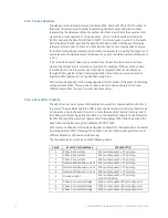
background image

GE

Grid Solutions

489

Generator Management Relay

COMMUNICATIONS GUIDE

Software Revision: 4.0x

GE Publication Code: GEK-106495H

GE Multilin Part Number: 1601-0149-A8

Copyright © 2017 GE Multilin Inc.

GE Grid Solutions

650 Markland Street

Markham, Ontario

Canada L6C 0M1

Tel: +1 905 927 7070   Fax: +1 905 927 5098

Internet: 

http://www.gegridsolutions.com

*1601-0149-A8*

Summary of Contents for Multilin 489

Page 1: ...are Revision 4 0x GE Publication Code GEK 106495H GE Multilin Part Number 1601 0149 A8 Copyright 2017 GE Multilin Inc GE Grid Solutions 650 Markland Street Markham Ontario Canada L6C 0M1 Tel 1 905 927...

Page 2: ......

Page 3: ...7 FUNCTION CODE 08 LOOPBACK TEST CG 8 FUNCTION CODE 16 STORE MULTIPLE SETPOINTS CG 8 FUNCTION CODE 16 PERFORMING COMMANDS CG 9 ERROR RESPONSES CG 10 MODBUS MEMORY MAP CG 11 MEMORY MAP INFORMATION CG 1...

Page 4: ...CGTOC II 489 GENERATOR MANAGEMENT RELAY COMMUNICATIONS GUIDE TABLE OF CONTENTS...

Page 5: ...with Belden 9841 RS485 wire The value of the terminating resistors should be equal to the characteristic impedance of the line This is approximately 120 for standard 22 AWG twisted pair wire Shielded...

Page 6: ...f a 1 byte Slave Address a 1 byte Function Code a variable number of Data Bytes depending on the Function Code and a 2 byte CRC code The terms Slave Address Function Code Data Bytes and CRC are explai...

Page 7: ...rror indicates than one or more bytes of the transmission were received incorrectly and thus the entire transmission should be ignored in order to avoid the 489 performing any incorrect operation The...

Page 8: ...onization is maintained by timing constraints The receiving device must measure the time between the reception of characters If three and one half character times elapse without a new character or com...

Page 9: ...yte values transmitted high order byte first Thus all 489 setpoints and actual values are sent as two bytes The maximum of 125 registers can be read in one transmission Function codes 03 and 04 are co...

Page 10: ...mentation Store Single Setpoint This command allows the master to store a single setpoint into the 489 memory The slave response to this function code is to echo the entire master transmission CRC low...

Page 11: ...ress 1 0B message for slave 11 Function Code 1 06 store single setpoint Data Starting Address 2 11 80 setpoint address 1180h Data 2 01 F4 data for address 1180h CRC low high 2 8D A3 computed CRC error...

Page 12: ...olding registers to be stored The 489 response to this function code is to echo the slave address function code starting address the number of Setpoints stored and the CRC Message Format and Example R...

Page 13: ...tion Slave Address 1 0B message for slave 11 Function Code 1 10 store setpoints Data Starting Address 2 11 80 data starting at 1180h Number of Setpoints 2 00 02 2 setpoints 4 bytes total Byte Count 1...

Page 14: ...sponse to an error other than CRC error will be SLAVE ADDRESS 1 byte FUNCTION CODE 1 byte with MSbit set to 1 EXCEPTION CODE 1 byte CRC 2 bytes The 489 implements the following exception response code...

Page 15: ...Actual Values or Setpoints register addresses 2 A Register area memory map addresses 0100h to 017Ch that contains the data at the addresses in the Register Index Register data that is separated in th...

Page 16: ...3003h This way the front port rear port and auxiliary port can read different events from the event recorder simultaneously CG 3 4 Waveform Capture The 489 stores up to 64 cycles of A D samples in a...

Page 17: ...N A F15 N A 0002 Product Software Revision N A N A N A F16 N A 0003 Product Modification Number 0 to 999 1 N A F1 N A 0010 Boot Program Revision N A N A N A F16 N A 0011 Boot Program Modification Num...

Page 18: ...D 1 to 12 1 F1 1 0242 Hottest Stator RTD Temperature 50 to 250 1 C F4 0 0243 Last Trip Data Bearing RTD 1 to 12 1 F1 1 0244 Hottest Bearing RTD Temperature 50 to 250 1 C F4 0 0245 Last Trip Data Other...

Page 19: ...RTD 4 Pickup 0 to 4 1 F123 0 02A0 RTD 5 Pickup 0 to 4 1 F123 0 02A1 RTD 6 Pickup 0 to 4 1 F123 0 02A2 RTD 7 Pickup 0 to 4 1 F123 0 02A3 RTD 8 Pickup 0 to 4 1 F123 0 02A4 RTD 9 Pickup 0 to 4 1 F123 0 0...

Page 20: ...nter Pickup 0 to 4 1 F123 0 0325 Breaker Failure Pickup 0 to 4 1 F123 0 0326 Trip Coil Monitor Pickup 0 to 4 1 F123 0 0327 VT Fuse Failure Pickup 0 to 4 1 F123 0 0328 Current Demand Pickup 0 to 4 1 F1...

Page 21: ...ide Angle 0 to 359 1 F1 0 0424 Phase B Neutral Side Angle 0 to 359 1 F1 0 0425 Phase C Neutral Side Angle 0 to 359 1 F1 0 0426 Phase A Differential Angle 0 to 359 1 F1 0 0427 Phase B Differential Angl...

Page 22: ...rature 52 to 250 1 F F4 52 04C1 RTD 1 Temperature 52 to 251 1 F F4 52 04C2 RTD 2 Temperature 52 to 251 1 F F4 52 04C3 RTD 3 Temperature 52 to 251 1 F F4 52 04C4 RTD 4 Temperature 52 to 251 1 F F4 52 0...

Page 23: ...to 251 1 F F4 52 0645 RTD 6 Maximum Temperature Fahrenheit 52 to 251 1 F F4 52 0646 RTD 7 Maximum Temperature Fahrenheit 52 to 251 1 F F4 52 0647 RTD 8 Maximum Temperature Fahrenheit 52 to 251 1 F F4...

Page 24: ...ization Trips 0 to 50000 1 F1 0 079C Analog Input 1 Trips 0 to 50000 1 F1 0 079D Analog Input 2 Trips 0 to 50000 1 F1 0 079E Analog Input 3 Trips 0 to 50000 1 F1 0 079F Analog Input 4 Trips 0 to 50000...

Page 25: ...0 1 F22 _ 10C0 Scratchpad 0 to 40 1 F22 _ 10E0 Scratchpad 0 to 40 1 F22 _ 489 SETUP CLEAR DATA 1130 Clear Last Trip Data 0 to 1 1 F103 0 1131 Clear Mwh And Mvarh Meters 0 to 1 1 F103 0 1132 Clear Peak...

Page 26: ...7 1 F210 0 1231 Asserted Digital Input State 0 to 1 1 F131 0 1232 Input Name 0 to 12 1 F22 _ 1238 Block Input From Online 0 to 5000 1 s F1 0 1239 General Input B Control 0 to 1 1 F105 0 123A Pulsed C...

Page 27: ...Relay Dwell Time 0 to 250 1 s F2 0 129B Assign Control Relays 1 5 0 to 4 1 F50 0 129C General Input E Control Events 0 to 1 1 F105 0 129D General Input E Alarm 0 to 2 1 F115 0 129E Assign Alarm Relays...

Page 28: ...sign Digital Input 0 to 7 1 F210 0 1361 Sequential Trip Type 0 to 1 1 F206 0 1362 Assign Trip Relays 1 4 0 to 3 1 F50 1 1363 Sequential Trip Level 2 to 99 1 Rated MW F14 5 1365 Sequential Trip Delay 2...

Page 29: ...65535 1606 FlexCurve Trip Time at 1 05 PU 0 to 65535 1 ms F1 65535 1607 FlexCurve Trip Time at 1 10 PU 0 to 65535 1 ms F1 65535 1608 FlexCurve Trip Time at 1 20 PU 0 to 65535 1 ms F1 65535 1609 FlexCu...

Page 30: ...t 5 80 PU 0 to 65535 1 ms F1 65535 1637 FlexCurve Trip Time at 5 90 PU 0 to 65535 1 ms F1 65535 1638 FlexCurve Trip Time at 6 00 PU 0 to 65535 1 ms F1 65535 1639 FlexCurve Trip Time at 6 50 PU 0 to 65...

Page 31: ...rve Shape 0 to 13 1 F128 0 1729 FlexCurve Trip Time at 1 03 PU 0 to 65535 1 ms F1 65535 172A FlexCurve Trip Time at 1 05 PU 0 to 65535 1 ms F1 65535 172B FlexCurve Trip Time at 1 10 PU 0 to 65535 1 ms...

Page 32: ...t 5 90 PU 0 to 65535 1 ms F1 65535 175C FlexCurve Trip Time at 6 00 PU 0 to 65535 1 ms F1 65535 175D FlexCurve Trip Time at 6 50 PU 0 to 65535 1 ms F1 65535 175E FlexCurve Trip Time at 7 00 PU 0 to 65...

Page 33: ...se Overcurrent Trip 0 to 2 1 F115 0 1831 Assign Trip Relays 1 4 0 to 3 1 F50 1 1832 High Set Phase Overcurrent Pickup 15 to 2000 1 CT F3 500 1833 High Set Phase Overcurrent Delay 0 to 10000 1 s F3 100...

Page 34: ...rfrequency Trip Level 2 2000 to 6000 1 Hz F3 5800 208C Underfrequency Trip Delay 2 1 to 50000 1 s F2 300 VOLTAGE ELEMENTS OVERFREQUENCY 20A0 Block Overfrequency From Online 0 to 5 1 s F1 1 20A1 Voltag...

Page 35: ...Trip Relays 1 4 0 to 3 1 F50 1 2109 Circle 2 Diameter 25 to 3000 1 s F2 350 210A Circle 2 Offset 10 to 3000 1 s F2 25 210B Circle 2 Trip Delay 1 to 100 1 s F2 50 VOLTAGE ELEMENTS DISTANCE ELEMENT 213...

Page 36: ...Assign Trip Relays 1 4 0 to 3 1 F50 1 2289 Low Forward Power Trip Level 2 to 99 1 Rated MW F14 5 228B Low Forward Power Trip Delay 2 to 1200 1 s F2 200 RTD TEMPERATURE RTD TYPES 2400 Stator RTD Type...

Page 37: ...523 RTD 5 Alarm Temperature 1 to 250 1 C F1 130 2524 RTD 5 Alarm Events 0 to 1 1 F105 0 2525 RTD 5 Trip 0 to 2 1 F115 0 2526 RTD 5 Trip Voting 1 to 12 1 F122 5 2527 Assign Trip Relays 1 4 0 to 3 1 F50...

Page 38: ...to 2 1 F115 0 2662 Assign Alarm Relays 2 5 1 to 4 1 F50 16 2663 RTD 10 Alarm Temperature 1 to 250 1 C F1 80 2664 RTD 10 Alarm Events 0 to 1 1 F105 0 2665 RTD 10 Trip 0 to 2 1 F115 0 2666 RTD 10 Trip V...

Page 39: ...5 2812 Time to Trip at 1 20 FLA 5 to 999999 1 s F10 5 2814 Time to Trip at 1 30 FLA 5 to 999999 1 s F10 5 2816 Time to Trip at 1 40 FLA 5 to 999999 1 s F10 5 2818 Time to Trip at 1 50 FLA 5 to 999999...

Page 40: ...Failure Level 5 to 2000 1 CT F3 100 2A23 Breaker Failure Delay 10 to 1000 10 ms F1 100 2A24 Breaker Failure Alarm Events 0 to 1 1 F105 0 MONITORING TRIP COIL MONITOR 2A30 Trip Coil Monitor Alarm 0 to...

Page 41: ...t 4 0 to 42 1 F127 0 ANALOG INPUT OUTPUT ANALOG OUTPUTS 2B04 Ia Output Current Minimum 0 to 2000 1 FLA F3 0 2B05 Ia Output Current Maximum 0 to 2000 1 FLA F3 125 2B06 Ib Output Current Minimum 0 to 20...

Page 42: ...aximum 0 to 9000 1 Hz F3 6100 2B3C Power Factor Minimum 99 to 100 1 F6 80 2B3D Power Factor Maximum 99 to 100 1 F6 80 2B3E Reactive Power Minimum 200 to 200 1 Rated F6 0 2B3F Reactive Power Maximum 20...

Page 43: ...1 F129 0 2C45 Analog Input 2 Units 0 to 6 1 F22 _ 2C48 Analog Input 2 Minimum 50000 to 50000 1 Units F12 0 2C4A Analog Input 2 Maximum 50000 to 50000 1 Units F12 100 2C4C Block Analog Input 2 From On...

Page 44: ...22 _ 489 TESTING SIMULATION MODE 2D00 Simulation Mode 0 to 3 1 F138 0 2D01 Pre fault To Fault Time Delay 0 to 300 1 s F1 15 489 TESTING PRE FAULT SETUP 2D20 Pre Fault Iphase Output 0 to 2000 1 CT F3 0...

Page 45: ...Of Events Since Last Clear 0 to 65535 1 N A F1 0 3003 Event Record Select 0 to 65535 1 N A F1 1 EVENT RECORDER SELECTED EVENT 3004 Cause Of Event 0 to 143 F134 0 3005 Time Of Event 2 Words N A N A N A...

Page 46: ...F1 0 30EA Vab Iab Angle 0 to 359 1 F1 0 WAVEFORM MEMORY SETUP 30F0 Waveform Memory Trigger Date N A N A N A F18 N A 30F2 Waveform Memory Trigger Time N A N A N A F19 N A 30F4 Frequency During Trace A...

Page 47: ...EMENT SIGNED LONG VALUE 2 DECIMAL PLACES 1st 16 bits High Order Word of Long Value 2nd 16 bits Low Order Word of Long Value Example 1234 56 stored as 123456 i e 1st word FFFE hex 2nd word 1DC0 hex F15...

Page 48: ...y 2 Bit 2 Relay 3 Bit 3 Relay 4 Bit 4 Relay 5 Bits 5 to 15 Not used F100 Unsigned 16 bit integer TEMPERATURE DISPLAY UNITS 0 Celsius 1 Fahrenheit F101 Unsigned 16 bit integer RS485 BAUD RATE 0 300 bau...

Page 49: ...DE 0 All Resets 1 Remote Reset Only 2 Keypad Reset Only F118 Unsigned 16 bit integer SETPOINT GROUP 0 Group 1 1 Group 2 F120 Unsigned 16 bit integer RTD TYPE 0 100 Ohm Platinum 1 120 Ohm Nickel 2 100...

Page 50: ...r ALARM TRIP STATUS 0 Not Enabled 1 Inactive 2 Timing Out 3 Active Trip 4 Latched Trip F124 Unsigned 16 bit integer PHASE ROTATION SELECTION 0 1 ABC 2 ACB F126 Unsigned 16 bit DISABLED ENABLED SELECTI...

Page 51: ...RTD 2 12 RTD 3 13 RTD 4 14 RTD 5 15 RTD 6 16 RTD 7 17 RTD 8 18 RTD 9 19 RTD 10 20 RTD 11 21 RTD 12 22 AB Voltage 23 BC Voltage 24 CA Voltage 25 Average Voltage 26 Volts Hertz 27 Frequency 28 Third Ha...

Page 52: ...CTION 0 Disabled 1 4 to 20 mA 2 0 to 20 mA 3 0 to 1 mA F130 Unsigned 16 bit integer PICKUP TYPE 0 Over 1 Under FC131 Unsigned 16 bit integer INPUT SWITCH STATUS 0 Closed 1 Open F132 Unsigned 16 bit in...

Page 53: ...34 Undervoltage Trip 35 Overvoltage Trip 36 Phase Reversal Trip 37 Overfrequency Trip 38 Not Used 39 Reactive Power Trip 40 Underfrequency Trip 41 Analog Input 1 Trip 42 Analog Input 2 Trip 43 Analog...

Page 54: ...Trip Counter Alarm 86 Breaker Failure Alarm 87 Current Demand Alarm 88 MW Demand Alarm 89 Mvar Demand Alarm 90 MVA Demand Alarm 91 Not Used 92 Analog Input 1 Alarm 93 Analog Input 2 Alarm 94 Analog I...

Page 55: ...Directional Alarm 135 High Set Phase Overcurrent Trip 136 Distance Zone 1 Trip 137 Distance Zone 2 Trip 138 Digital Input Waveform Trigger 139 Serial Waveform Trigger 140 IRIG B Failure 141 Running H...

Page 56: ...3 AUXILIARY bit 3 4 AUXILIARY bit 4 5 ALARM bit 5 6 SERVICE bit 6 to bit 15 Not Used F142 Unsigned 16 bit integer THERMAL MODEL CURVE STYLE SELECTION 0 Standard 1 Custom 2 Voltage Dependent F148 Unsig...

Page 57: ...ltage or Offline F206 Unsigned 16 bit integer SEQUENTIAL TRIP TYPE 0 Low Forward Power 1 Reverse Power F207 Unsigned 16 bit integer SWITCH STATUS 0 Open 1 Shorted F208 Unsigned 16 bit integer UNDERVOL...

Page 58: ...ne Current 512 counts 1 CT 4 Neutral End Phase A Line Current 512 counts 1 CT 5 Neutral End Phase B Line Current 512 counts 1 CT 6 Neutral End Phase C Line Current 512 counts 1 CT 7 Phase A to Neutral...

Page 59: ...6 bit integer BREAKER STATE 0 52 Closed 1 52 Open Closed F219 Unsigned 16 bit integer STEP UP TRANSFORMER TYPE 0 None 1 Delta Wye F220 Unsigned 16 bit integer IRIG B TYPE 0 None 1 DC Shift 2 Amplitude...

Page 60: ...ut Object 10 variation 2 Binary Counter Object 20 variations 5 and 6 Frozen Counter Object 21 variations 9 and 10 Analog Input Object 30 variations 1 2 3 and 4 Analog Input Change Object 32 variations...

Page 61: ...er Always Sometimes Configurable Pulse Off Never Always Sometimes Configurable Latch On Never Always Sometimes Configurable Latch Off Never Always Sometimes Configurable See Binary Control Relay Outpu...

Page 62: ...ut All Variations 1 06 10 2 Binary Output Status 1 00 01 06 129 00 01 12 1 Control Relay Output Block 3 4 5 6 17 28 129 17 28 20 0 Binary Counter All Variations 1 7 8 9 10 06 129 00 01 20 5 32 Bit Bin...

Page 63: ...returned for the object in a response when no specific variation is specified in a request Table CG 4 Default Variations Object Description Default Variation 1 Binary Input Single Bit 1 2 Binary Input...

Page 64: ...s 1 9 Loss Of Field Fault Active Class 1 10 VT Failure Detected Class 1 11 Breaker Failure Detected Class 1 12 Relay 1 Trip Operated Class 1 13 Relay 2 Auxiliary Operated Class 1 14 Relay 3 Auxiliary...

Page 65: ...ential Trip Active or Latched Class 1 56 Undervoltage Trip Active or Latched Class 1 57 Overvoltage Trip Active or Latched Class 1 58 Volts Hertz Trip Active or Latched Class 1 59 Phase Reversal Trip...

Page 66: ...102 Assignable Input 3 Alarm Active or Latched Class 1 103 Assignable Input 4 Alarm Active or Latched Class 1 104 Assignable Input 5 Alarm Active or Latched Class 1 105 Assignable Input 6 Alarm Activ...

Page 67: ...Latched Class 1 138 Trip Coil Monitor Alarm Active or Latched Class 1 139 VTFF Alarm Active or Latched Class 1 140 Current Dmd Alarm Active or Latched Class 1 141 MW Demand Alarm Active or Latched Cl...

Page 68: ...the only valid control is Close Pulse On 41 hex This is used to initiate the function e g Reset associated with the point Any value in the Control Code field not specified above is invalid and will b...

Page 69: ...ly off CG 5 3 Binary Frozen Counter Objects 20 21 Table CG 7 Counters Point List INDEX ROLLOVER POINT DESCRIPTION 0 50000 Number of Breaker Operations 1 50000 Number of Thermal Resets 2 50000 Number o...

Page 70: ...d have had their upper and lower 16 bit components assigned to separate points Where indicated refer to the appropriate note following the table for more detail 20 50000 Number of Reactive Power Trips...

Page 71: ...Trip Current Class 1 Notes 3 6 12 F1 Phase C Pre Trip Current Class 1 Notes 3 6 13 F1 Phase A Pre Trip Differential Current Class 1 Notes 3 6 14 F1 Phase B Pre Trip Differential Current Class 1 Notes...

Page 72: ...10 44 F10 Pre Trip Third Harmonic Neutral Voltage tenths of a volt Class 1 Notes 3 10 45 F2 Pre Trip Vab Iab loss of excitation impedance Class 1 Note 3 46 F1 Pre Trip Vab Iab Angle loss of excitatio...

Page 73: ...ss 2 Note 10 74 F1 Third Harmonic Neutral Voltage volts Class 2 Note 10 75 F10 Third Harmonic Neutral Voltage tenths of a volt Class 2 Note 10 76 F1 Third Harmonic Terminal Voltage volts Class 2 Note...

Page 74: ...F1 kVA Demand Class 2 Note 8 108 F1 Peak Current Demand Class 2 Note 7 109 F1 Peak MW Demand Class 2 Note 8 110 F1 Peak kW Demand Class 2 Note 8 111 F1 Peak Mvar Demand Class 2 Note 8 112 F1 Peak kvar...

Page 75: ...registers which are only accessible via Modbus Refer to User Definable Memory Map Area on page CG 11 for more information Changes in User Map Value points never generate event objects Note that it is...

Page 76: ...nalog inputs should be configured to operate within the range 32768 to 32767 10 Each neutral voltage quantity is available at two different points with two different scale factors volts and tenths of...

Page 77: ...t 2 data rate 2 error responses 10 passcode 13 CRC 16 3 CYCLIC REDUNDANCY CHECK see CRC 16 D DATA FORMATS MEMORY MAP 42 DATA FRAME FORMAT 2 DATA PACKET FORMAT 2 DATA RATE 2 DEFAULT VARIATIONS 59 DNP d...

Page 78: ...ction code 04 5 function code 05 6 function code 06 6 function code 07 7 function code 08 8 function code 16 8 loopback test 8 performing commands 9 read actual values 5 read device status 7 read setp...

Reviews: